So far in this series we have discussed the Playpause concept and design, and how to make PCBs, using Playpause as an example. Now I want to show how to assemble a Playpause, and how to load the software using a bed-of-nails jig.
Surface mount technology is within reach of everyone. There's no special technology being used here. The iron is a normal 25W soldering iron, it's just normal electronics solder, and the soldering in the photos is being done by my 11-yo son, who has barely soldered before. Thanks Tim!
The first thing to start with is the ATtiny85 microcontroller. When I was a lad, we were told to add the semiconductors to our project last, because of the danger of damage from static. The reason I'm putting the microcontroller on first is because we need to program the chip, and the other components can interfere with programming.
Here's a pic of the chip perched on the board. I've lined up the pins with the PCB pads. Since we will first solder just one pad, it's not critical that all pads are lined up, just the corner pad that gets soldered first:
 |
| Chip perched on board |
Unless the chip is held in position, it is likely to be moved out of place when touched by the soldering iron. A totally excellent way of holding the chip in place during soldering is to use one tine of a small gardening fork, as described by
Jonathan Oxer:
 |
| Pressure applied with mini garden fork |
Next up, soldering the first pin:
 |
| Soldering the first pin |
The aim is for the soldering iron to touch both the pad and the pin, so both get heated, for about a second. Then lightly feed a little solder onto the joint (not onto the iron) until the solder flows between the pad and pin. Then remove the iron, and allow the molten solder to solidfy. Make sure the joint is not moved until the solder is set. Surface mount components are very small, and don't take well to being heated for long periods, so try to minimise the amount of time they are in contact with the iron.
After the first pin is soldered, you can gently rotate the chip to get all the pins aligned.
 |
| One pin soldered, the chip can be aligned |
After the pins are aligned, the rest of the pins can be soldered:
 |
| Soldering the rest of the pins |
Don't worry if you bridge pins with too much solder. In fact, one good way of soldering fine pitch chips is to deliberately use too much solder, then remove the excess with desoldering braid:
 |
| Fixing solder bridges with soldering braid |
Now that the microcontroller is soldered on, we can program in the firmware. I am using Tom Long's fantastic
USBTiny mkII programmer. Also in this picture is a SparkFun
AVRStick, which was my original inspiration for both the USB Doodad and Playpause projects. Thanks SparkFun for the AVRStick, and thanks Objective Development for
V-USB!
 |
| AVRStick and programmer |
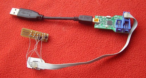
To program the Playpause, I'm using a “bed-of-nails” made of “pogo pins” to connect the 6 wires of the ISP header to the micro. You can find out more about pogo pins and making bed-of-nails jigs at this
SparkFun tutorial.
To line up the pins with the pads on the circuit board, I made a sleeve out of three pieces of cardboard, glued together as a sandwich. Holes drilled in the top piece of cardboard line up with the pads on the PCB. I slide the PCB into the sleeve, then using one hand, I can hold the bed of nails and the sleeve together. With the other hand, I can press Enter on my computer to run the command to copy the firmware to the micro, and set the right fuses (for example, the fuse which turns on the clock PLL that I mentioned
earlier).
 |
| Playpause with bed of nails. The PCB in this pic doesn't have a chip, but of course for programming it would need to have one. |
Programming:
FIXME
The PCB traces at one end of the board are just the right shape to work as a USB connector. But the copper isn't very thin, and if used often, the other part of the connector (the part in your PC) will wear away the copper. To avoid this, you can tin the USB tracks with solder:
 |
| Tinning USB connector traces |
After the controller is programmed, and the USB traces are tinned, we can add the other components as per this chart:
You can use the gardening fork on all the components except for the diodes, if the diodes are cylindrical. For the diodes, you can ask a friend to hold the diode in position with a small screwdriver.
And now a small admission: When I was copying and pasting the layout to make ten boards, I accidentally deleted a track. That track was omitted on all ten boards I made. So here a small wire is being soldered on to act as the missing track. All the other components have already been soldered.
 |
| All passives soldered, doing the switch (extra wire) |
When I was developing Playpause, I made a few mistakes in the firmware, which meant I needed to correct and update the firmware. But because I'd already loaded all the components onto the PCB, I couldn't put the PCB back into the programming sleeve. So as an alternative, I direct-wired a 6-pin ISP header to the PCB.
Note that having additional components can interfere with the programmer, but in this case, it seems to work:
 |
| Playpause hot-wired to programmer |
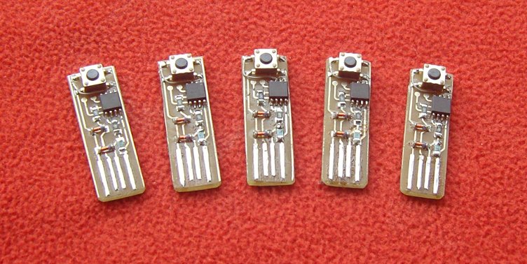
I made ten of these Playpause boards and took five of them to a friend's place for a craft-and-chat day. Most of the soldering on these boards was done by people who had never done any kind of soldering before, thus proving that surface mount soldering doesn't require any particular skill or dexterity, but just some instruction and guidance.
 |
| Five completed playpauses |
So, I now have a Playpause to use at work when I'm listening to music, and I can now apply my knowledge of making PCBs and doing bed-of-nails programming to the USB Doodad. Maybe you can too. If you have any questions, or want help making a Playpause or PCBs, ask me.


This comment has been removed by the author.
ReplyDeleteGreetings,
ReplyDeleteFirst, I wanted to introduce myself, I am Algen Dela Cruz and I worked as an administrator at EEWeb, an Electrical Engineering community website. I wanted to reach out to you to ask if we can feature your website on EEWeb. We checked your website and we found that it fits our criteria, we believe that your website would be an interest to our community members. At the same time maybe we can exchange website links? Is this of interest to you?
Looking forward to hearing from you soon.
Best,
Algen
This is a really nice piece of information.
ReplyDeleteI liked it very much, thanks for sharing it here.
If you are little bit familiar with electronics things then you may know the importance of solder.
So you can check best solder for electronics here.