Wednesday, June 8, 2011

Playpause 3: Assembly and programming

So far in this series we have discussed the Playpause concept and design, and how to make PCBs, using Playpause as an example. Now I want to show how to assemble a Playpause, and how to load the software using a bed-of-nails jig.

Surface mount technology is within reach of everyone. There's no special technology being used here. The iron is a normal 25W soldering iron, it's just normal electronics solder, and the soldering in the photos is being done by my 11-yo son, who has barely soldered before. Thanks Tim!

The first thing to start with is the ATtiny85 microcontroller. When I was a lad, we were told to add the semiconductors to our project last, because of the danger of damage from static. The reason I'm putting the microcontroller on first is because we need to program the chip, and the other components can interfere with programming.

Here's a pic of the chip perched on the board. I've lined up the pins with the PCB pads. Since we will first solder just one pad, it's not critical that all pads are lined up, just the corner pad that gets soldered first:

Chip perched on board
Unless the chip is held in position, it is likely to be moved out of place when touched by the soldering iron. A totally excellent way of holding the chip in place during soldering is to use one tine of a small gardening fork, as described by Jonathan Oxer:
Pressure applied with mini garden fork
Next up, soldering the first pin:
Soldering the first pin
The aim is for the soldering iron to touch both the pad and the pin, so both get heated, for about a second. Then lightly feed a little solder onto the joint (not onto the iron) until the solder flows between the pad and pin. Then remove the iron, and allow the molten solder to solidfy. Make sure the joint is not moved until the solder is set. Surface mount components are very small, and don't take well to being heated for long periods, so try to minimise the amount of time they are in contact with the iron.
After the first pin is soldered, you can gently rotate the chip to get all the pins aligned.

One pin soldered, the chip can be aligned
After the pins are aligned, the rest of the pins can be soldered:
Soldering the rest of the pins
Don't worry if you bridge pins with too much solder. In fact, one good way of soldering fine pitch chips is to deliberately use too much solder, then remove the excess with desoldering braid:
Fixing solder bridges with soldering braid
Now that the microcontroller is soldered on, we can program in the firmware. I am using Tom Long's fantastic USBTiny mkII programmer. Also in this picture is a SparkFun AVRStick, which was my original inspiration for both the USB Doodad and Playpause projects. Thanks SparkFun for the AVRStick, and thanks Objective Development for V-USB!
AVRStick and programmer
To program the Playpause, I'm using a “bed-of-nails” made of “pogo pins” to connect the 6 wires of the ISP header to the micro. You can find out more about pogo pins and making bed-of-nails jigs at this SparkFun tutorial.

To line up the pins with the pads on the circuit board, I made a sleeve out of three pieces of cardboard, glued together as a sandwich. Holes drilled in the top piece of cardboard line up with the pads on the PCB. I slide the PCB into the sleeve, then using one hand, I can hold the bed of nails and the sleeve together. With the other hand, I can press Enter on my computer to run the command to copy the firmware to the micro, and set the right fuses (for example, the fuse which turns on the clock PLL that I mentioned earlier).

Playpause with bed of nails.  The PCB in this pic doesn't have a chip, but of course for programming it would need to have one.

 Programming:


FIXME

The PCB traces at one end of the board are just the right shape to work as a USB connector. But the copper isn't very thin, and if used often, the other part of the connector (the part in your PC) will wear away the copper. To avoid this, you can tin the USB tracks with solder:

Tinning USB connector traces
After the controller is programmed, and the USB traces are tinned, we can add the other components as per this chart:


You can use the gardening fork on all the components except for the diodes, if the diodes are cylindrical. For the diodes, you can ask a friend to hold the diode in position with a small screwdriver.

And now a small admission: When I was copying and pasting the layout to make ten boards, I accidentally deleted a track. That track was omitted on all ten boards I made. So here a small wire is being soldered on to act as the missing track. All the other components have already been soldered.

All passives soldered, doing the switch (extra wire)
When I was developing Playpause, I made a few mistakes in the firmware, which meant I needed to correct and update the firmware. But because I'd already loaded all the components onto the PCB, I couldn't put the PCB back into the programming sleeve. So as an alternative, I direct-wired a 6-pin ISP header to the PCB.

Note that having additional components can interfere with the programmer, but in this case, it seems to work:

Playpause hot-wired to programmer
I made ten of these Playpause boards and took five of them to a friend's place for a craft-and-chat day. Most of the soldering on these boards was done by people who had never done any kind of soldering before, thus proving that surface mount soldering doesn't require any particular skill or dexterity, but just some instruction and guidance.

Five completed playpauses


So, I now have a Playpause to use at work when I'm listening to music, and I can now apply my knowledge of making PCBs and doing bed-of-nails programming to the USB Doodad. Maybe you can too. If you have any questions, or want help making a Playpause or PCBs, ask me.

Playpause 2: Making PCBs at home

For a long time, I've wanted to make PCBs at home.


In the past, I used to make my own electronics project using stripboard and perfboard. This is reliable, if not slow. But a stripboard design doesn't really lend itself to being constructed by others.

In the past year I've started working with surface mounted devices. SMD doesn't work very well on stripboard, so it becomes not just desirable but necessary to make PCBs. I have put off learning how to do it for a long time, but a month or so ago, I finally got the time to give it a go. This article covers what I currently do, and I'm writing about it here in the hope it will help others.

There are three main ways of making circuit boards at home. The first is via the “toner transfer” method. I have tried that in the past, but never been able to reliably make a circuit board greater than about a square inch: I've always had a lot of trouble getting the toner 100% fused to the PCB without cracking or smudging.

The second is by using a CNC mill to mill away undesired copper, leaving copper tracks. With the imminent completion of the CNC mill at our hackerspace, or if I one day build a CNC mill using components salvaged from old DVD drives, that might be a possibility. However for the moment I don't have access to a CNC mill, so I can't use that method.

The third is the photographic method. With this method, a special copper-clad PCB is covered by a film of UV-sensitive dye. Exposing the dye to ultraviolet light through artwork printed on transparent paper will leave some regions of dye exposed, and some regions unexposed. A developer chemical will remove the exposed areas, leaving the dye in the form of green tracks on the board. Then the board is etched in a chemical etchant, which removes the copper which is not protected by the dye. Finally, the dye is removed, leaving copper tracks.

In this article I'll show how to use the photographic method, although I might try the toner transfer and CNC methods again in the future.

The UV-sensitive PCB stock I'm using is sold by Kinsten, and is available in single- and doubled-sided variants. Here is the Kinsten PCB, plus the developer (Kinsten DP-50), etchant (ammonium persulphate), and a scrubbing pad:

Kinsten, etchant, developer and scrubber

In order to generate the UV light, I made an exposer box using nearly 100 UV LEDs. For an enclosure, I cut up and resized a cardboard box. The box is lined with aluminium foil to reflect light towards the board I'm exposing, and the light has to travel through two diffusers of transparent paper.

Here's a picture of the LED array:

Exposer's UV array, LED side


And here's a picture of how I wired up the LEDs:

Exposer's UV array, wiring side

(The two halves are wired differently because the second board is somewhat smaller than the first board, and wouldn't allow the straight-forward row-and-column arrangement I used on the first board).

The specifications for the LEDs say the forward voltage is about 3V. The wiring of the boards configures the LEDs into many parallel strings of four LEDs. I power the exposer with a 12V power supply. I have adjusted the trimpot on the power supply to get a voltage that gives me a current of 25mA through each LED. The LEDs do get quite warm after running for a while. Here's a picture of the exposer working:

Exposer powered up showing UV


NOTE: The LEDs produce a bluish-purple light, but this is not ultraviolet, it's a consequence of the spectrum from the LEDs being spread out somewhat. Our eyes cannot perceive ultraviolet light, yet it is harmful to our eyes. If you are working with ultraviolet light, try to limit how much UV gets into your eyes, or you may have to bear gritty and sore eyes for a few days. UV filtering sunglasses might be a good idea.

I print the artwork for the board on tracing paper I bought from the newsagent. I print it with a laser printer, and in the printer settings dialog I set the density to be as dark as possible. I usually print right-way-around on normal paper to verify that all the parts fit the board, then I print on the transparency in reverse. If I used a normal printout, there'd be a layer of transparency between the toner and the dye. This can cause blurring, as the UV light can diffuse to under the artwork. Mirroring the image means the toner can be right up against the dye.

Tracing paper with artwork


A few weeks ago when I first started this exercise, I didn't know how long to do the UV exposure for. I made some board artwork of ten TQFP-32 footprints in a row, with some lines of different thicknesses. I put the artwork and the PCB on the exposer with a piece of cardboard. Every fifteen seconds I slid the cardboard across by one TQFP, so that by the time two minutes and thirty seconds had elapsed, I had a row of footprints that had been exposed for various times, from 0:15 to 2:30. When I later developed the exposed PCB, what I found was that for my exposer, no pattern emerged until an exposure time of 2:00, and by 2:30 the pattern had developed very nicely. I have since made PCBs with exposure times of 3:00 to 3:30, and they have turned out very nicely.

Some people I've spoken to said I wouldn't be able to reliably make the 0.016” tracks I was hoping for. The good news is that tracks down to 0.010” come out just perfectly, and tracks down to 0.008” (0.2mm) appear very achievable. I think the biggest limiting factor is the quality of the artwork: I can trace small irregularities in the finished PCB to slight imperfections in the artwork, either because of dust or because there is a small hole in the toner. It seems that the toner binds to some places on the transparency better than others.

When doing the exposure, you need some way to keep the artwork flat against the PCB. I use a glass-topped coffee table. I tape the exposer to the bottom side of the coffee table, and put the artwork and PCB on top, held down by a heavy book. I always clean the glass with glass cleaner before doing the exposure.

The dye on the Kinsten PCB is protected by a white plastic film. Just before exposing, I peel off the film, revealing the blue-green dye. I do the exposing well away from the window, as otherwise ultraviolet from the sun may spoil the exposure.

I don't have a picture of a PCB being exposed, because when I'm doing the exposure, I have my hands full with holding the exposer and watching the exposure time.

At the end of the exposure time, I cover the PCB to prevent stray UV light from damaging the exposure. If you look carefully, you should be able to see the pattern of tracks as a very faint yellow hue on the blue-green dye. If you can't see it, it might indicate an exposure problem.

Here I'm developing the board in developer solution:

Developing Playpause boards in developer solution


This is 15g of Kinsten DP-50 developer, in 250ml of water. The developer doesn't have to be hot or warm, but having it warm speeds things up a little. While exposing the boards, I rock the container from side to side. As the exposed dye comes off, it makes patterns in the water like smoke.

Here are the boards after they have been developed. I wash them in water, then dry them, being careful not to scratch the ink.

Developed boards


Now it's time to etch the boards. There are three main chemicals hobbyists use to etch boards. In order of how often they're used, they are ferric chloride, ammonium persulphate, and a mixture of hydrochloric acid and peroxide bleach. Each method has advantages and disadvantages:

Method Advantages Disadvantages
Ferric chloride Etches at room temperature. Horrid yellowy-brown colour stains everything it comes in contact with. Best done outside using things you'll never use again.
Ammonium persulphate Does not stain. Easy to tell how much copper the solution contains, and therefore whether the solution is still ok. Only etches at 60-70ÂșC and above. Can be a bit fiddly to get the right concentration.
HCl/H2O2 Can be recharged by bubbling air through it with an aquarium pump, which means less chemicals to buy, and less to dispose of. Two rather nasty corrosive chemicals, so care must be taken.


There is a lot of information about making circuit boards on the Internet. For example, here's an interesting article about using just a tablespoon of ferric chloride per board, which I think I will do next time. There is also lots of information on the various techniques here.

I have been using ammonium persulphate, which needs to be kept hot in order for it to work. I put the etchant in a foam ice-cream container, and heat it in the microwave until I can just see vapour. (You don't want to do this too long, as you probably don't want a film of ammonium persulphate eating away the metal parts of your microwave). The foam of the container helps keep the etchant hotter for longer, although it will probably not stay hot enough for the 5-10 minutes needed to etch the board. So, bad boy that I am, I admit to re-heating the etchant in the microwave, even with the PCB in the etchant. I haven't heard any of the arcing that usually happens if you microwave a dish that accidentally has a bit of aluminium foil in it.

Anyway, here's a pic of the etch in progress:

Etching boards. Blue is copper ions


I etch the boards for long enough that large blank areas of the board have completely lost their copper, but not so long that the etchant has had time to start undercutting the tracks of my circuit. After etching, I wash the boards in cold water.

When you are finished, you will have a container of etchant. If you are a cheapskate hobbyist like me, you can save the etchant in a bottle for next time. The etchant is generally good for a couple of boards, depending on how much etchant there is, and the size of the boards you've etched. But there will come a time (for ammonium sulphate, this is when the solution has become such a dark blue that you don't think it could become any bluer) when you have to dispose of the etchant. The problem is that copper ions are an environmental toxin. Apart from taking the etchant to your local waste disposal centre, one idea is to use a paintbrush to paint the etchant onto newspaper, and let the newspaper dry. Then you can dispose of this newspaper in your garbage.

Obviously, the purpose of the etchant is to eat away metals. The problem is that any etchant that gets splashed onto metal (for example, if you're working near a sink, or if you are foolish enough to tip the etchant down the drain) will keep etching. I'm told a drop of etchant will create pinholes in your sink faster than you'd think. So it's probably best to keep the etchant well away from sinks and drains. I do my etching outside, and have a plastic bucket of cold water to do my rinsing in.

After the board is etched, the areas where you want copper are still covered in the dye. This dye can be removed with acetone, or scrubbed off with a scouring pad (don't use steel wool, as the iron may react with the copper over time). The problem is that this leaves the copper exposed to the air, which will then quickly tarnish. There are several ways to treat this. One way is to spray the board with special solder-through lacquer. Another way is to use a special compound to “tin” the board with a metal that doesn't corrode as quickly as copper. I use Cool-amp silver plating powder from ultrakeet.com.au. I haven't yet worked out how to get a great, easy result with this product, but it's better than nothing.  An alternative to Cool-amp is Liquid Tin, (and in .au, here), which I haven't used.  Expensive, but I know folks who swear by it, and say it lasts years.  Sounds worth it to me.

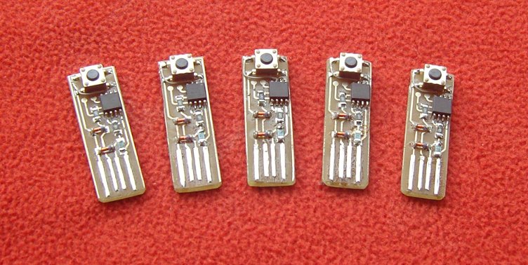
Here are the etched and tinned boards:

Etched and tinned playpause boards


After tinning the boards, I cut them up using an abrasive wheel in my Dremel tool:

Etched, tinned and cut playpause boards, with artwork


Then I file the edges of the boards, and give them a bevel. The boards are then ready for use.

So there you have it: PCBs from artwork to finished. I hope this is interesting and useful. Special thanks to Ross McK, who showed me how to do it. Ross is a great guy and a fine engineer, and he has taught me a lot.

Coming next: Playpause assembly and programming


Update: Here's another very interesting page where the author also adds a solder-stop mask.  His German heritage really shows, as his boards are wonderful!

Thursday, May 19, 2011

Playpause 1: Design

Ever needed to quickly pause the music or movie that's playing on your computer? Maybe someone is calling you, or you're trying to listen to something else. Hunting around for the pause button with a mouse takes several seconds. What if you could instantly pause with a single button press?
When a USB Doodad gets shipped to someone, it will have a presoldered AVR chip. Somehow I need to get the bootloader into the AVR chip without soldering anything else to the board. The natural way of doing this is via a bed of nails, as I mentioned in Doodad 4.

I have been messing around with bed-of-nails recently, via a little subproject I've been working on called "Playpause":

On top is the Playpause board.
Below is the board for doing bed-of-nails testing.

While the USB Doodad is designed to be a general purpose reprogrammable device, Playpause just does one job: It is a tiny USB device which pretends to be a HID keyboard. But unlike most keyboards, playpause only knows how to send one keycode: The play/pause keycode you'll get from pressing the play/pause button on a multimedia keyboard. Thus with one of these plugged in, you can play and pause your music or movie player without having to get busy with the mouse.  It's small, inexpensive, and easy to build.

(You can find the source code and the KiCad design files here.  TODO: I'm currently working out how to do git submodules so I can park the V-USB code inside playpause, because that's how V-USB likes to be used).

Because it sends a standard USB HID Keyboard keycode, PlayPause will work with any operating system, and doesn't need to have drivers installed. (Although at present it doesn't work with the Mac. I wish I knew why).

Playpause uses the V-USB software USB stack. This is a good choice for AVR projects that you want to be USB-capable, even if the AVR micro you're using doesn't have support for USB in hardware. But there's a catch: V-USB implements USB by using software, which means that when processing USB traffic, the micro can't do anything else.  In practice, this is fine if the task you want your micro to do isn't timing or latency critical, and for this V-USB works very nicely.

Playpause uses surface mount soldering, and the micro I'm using is the 8-pin ATtiny85 in a SOIC-8 package . The pitch on these pins is less than half of an ATtiny85 in PDIP format, which is why Playpause can be made so conveniently small.

While the USB port provides 5V for your device to run on, the USB signalling is done at 3.3V.  This means that every USB project needs to handle this difference somehow.  There are two basic ways of doing this.  The first is to regulate the 5V down to 3.3V, then feed your micro on 3.3V.  This can be done with a linear regulator, or by using the voltage drop across two ordinary diodes.  The second is to run your micro at 5V, but clamp the USB signals to 3.3V.  This can be done with two 3.6V zener diodes, or I've seen some designs (for example the SparkFun AVRStick) that use the forward voltage drop of blue LEDs.  The reason why 3.6V zener diodes are used instead of 3.3V, is that at the frequencies USB runs at, and given the capacitance of a zener diode, the 3.6V zener effectively clamps at 3.3V.  For Playpause, I'm taking the second approach, as shown in “solution B” on the V-USB hardware design page.

Playpause has no external crystal or resonator.  Instead, the clock for the AVR chip is generated onboard using the ATtiny85's RC oscillator.  This presents two problems.  The first is that the RC oscillator is uncalibrated, and may not produce the accurate or stable frequency needed to bit-bang USB packets.  The second problem is that the minimum frequency at which the controller can run V-USB is 12MHz, which is above the nominal 8MHz of the RC oscillator.  How is this situation resolved?

The first problem can be solved by noting that certain parts of the USB protocol take a precise amount of time.  The V-USB software in Playpause can count how many CPU cycles this known time period takes, then from this calculate a calibration value for the RC oscillator. That calibration value then makes sure the RC oscillator produces an exact frequency.

The solution to the second problem lies in the ATtiny85's built-in digital PLL. This circuit has a multiply-by-8 function, so that an input of 8.25MHz from the RC oscillator (8MHz but tweaked up a bit via calibration) gets boosted by the PLL to 66MHz. This frequency is then fed through the clock prescaler, which divides it by 4, to give 16.5MHz, which a frequency supported by V-USB. Curiously, only certain Atmel chips have a PLL, including the ATtinyx5, but excluding the ATmegax8 range. Very useful indeed!

Things to do


Macs


For some reason, Playpause currently doesn't work with Mac computers. My Mac-using friends tell me that the Playpause is able to identify itself correctly, but for some reason MacOS doesn't believe it has a driver to handle the multimedia keypresses Playpause is sending. To try to solve this problem, my plan is to plug in a commercial multimedia keyboard, and sniff the codes it sends when the pause button is sent. That's what I originally did when developing the software, but perhaps there's something I missed, particularly in how multimedia keyboards identify themselves. Either way, it seems that only a software change would be needed to fix the problem.

Suspend


The USB standard says that when the computer suspends, USB devices should put themselves into a low power mode. I'm not currently doing that, so my board is using more power than is strictly necessary. To fix this, I'd set up the processor to sleep until a USB interrupt is received, and if it's not the wakeup condition, go back to sleep.

Code cleanup


The code that's in Git is a direct offshoot of my work on the USB Doodad. As such, it's cluttered with a bunch of things which are not relevant to Playpause. Some janitorial work here would be good.

Coming next: Making PCBs at home

Rumours of this blog's death are premature

Wow, has it really been three months since I last blogged? Hard to believe. I have been so busy hacking on cool stuff. Previously my blog posts have been to demonstrate something, which is all well and good when one has something to demonstrate. I think I might do more blog posts which are stream-of-consciousness.

In particular, the USB Doodad project is not dead. I have been working on it constantly, just not writing about it.

Anyway, expect to see a rash of new articles soon.

Thursday, February 10, 2011

USB Doodad 6: Bootloader

Now that we know USB is working, it's time to get the bootloader working.  The bootloader is called "bootloadHID", and can be found here:

  http://www.obdev.at/products/vusb/bootloadhid.html

I downloaded bootloadHID and extracted it:

[mjd@onza src]$ wget -q http://www.obdev.at/downloads/vusb/bootloadHID.2010-07-29.tar.gz
[mjd@onza src]$ tar -xzf bootloadHID.2010-07-29.tar.gz
[mjd@onza src]$

I have made some changes to the bootloader source and config:
  • We're using different pins for the USB.
  • I want the LEDs to blink to show something's happening.  The blinking is different depending on whether the bootloader is in program mode, or has handed control to the application.
  • Our bootloader program mode switch is connected to an analog input rather than a digital input.  Therefore I had to add code to read an analog value. 
  • Once the bootloader is in program mode, I want it to stay in program mode after the button is released.  (In the stock code, you have to hold down the button constantly in order to program the MCU).
  •  I've changed the MCU type, the fuses, the execution start address and the right command to run avrdude for my USB programmer:

--- bootloadHID.2010-07-29.orig/firmware/bootloaderconfig.h
+++ bootloadHID.2010-07-29/firmware/bootloaderconfig.h
@@ -43,7 +43,7 @@
 /* This is the port where the USB bus is connected. When you configure it to
  * "B", the registers PORTB, PINB and DDRB will be used.
  */
-#define USB_CFG_DMINUS_BIT      0
+#define USB_CFG_DMINUS_BIT      3
 /* This is the bit number in USB_CFG_IOPORT where the USB D- line is connected.
  * This may be any bit in the port.
  */
@@ -106,6 +106,7 @@
 #ifndef __ASSEMBLER__   /* assembler cannot parse function definitions */
 #include <util/delay.h>

+#if 0
 static inline void  bootLoaderInit(void)
 {
     PORTD = 1 << 3; /* activate pull-up for key */
@@ -113,6 +114,7 @@
 }

 #define bootLoaderCondition()   ((PIND & (1 << 3)) == 0)   /* True if jumper is set */
+#endif

 #endif

--- bootloadHID.2010-07-29.orig/firmware/main.c
+++ bootloadHID.2010-07-29/firmware/main.c
@@ -81,8 +81,15 @@

 static void (*nullVector)(void) __attribute__((__noreturn__));

+static inline void setLed(const int i)
+{
+    PORTC &= ~(_BV(PC0) | _BV(PC1) | _BV(PC2) | _BV(PC3));
+    PORTC |= i & (_BV(PC0) | _BV(PC1) | _BV(PC2) | _BV(PC3));
+}
+
 static void leaveBootloader()
 {
+    setLed(15);
     DBG1(0x01, 0, 0);
     cli();
     boot_rww_enable();
@@ -215,9 +222,68 @@
     sei();
 }

+#define ADC_CHANNEL                    6
+#define ADC_ENABLED                     (1 << ADEN)
+#define ADC_SINGLE_CONVERSION           (0 << ADATE)
+#define ADC_CONV_COMPLETE_INTR_OFF      (0 << ADIE)
+#define ADC_PRESCALE_128                ((1 << ADPS2) | (1 << ADPS1) | (1 << ADPS0))
+#define ADC_REFERENCE_AVCC              (0 << REFS1 | 1 << REFS0)
+#define ADC_RIGHT_ADJUSTED              (0 << ADLAR)
+#define ADC_START_CONV                  (1 << ADSC)
+#define ADC_CONV_IN_PROGRESS            (1 << ADSC)
+#define ADC_CONV_INTFLAG                (1 << ADIF)
+
+static inline void ADC_Init()
+{
+    // Write 0 to power up ADC, 1 to power down
+    PRR &= ~PRADC;
+
+    ADCSRA = ADC_ENABLED | ADC_SINGLE_CONVERSION | ADC_CONV_COMPLETE_INTR_OFF | ADC_PRESCALE_128;
+
+    ADMUX = ADC_REFERENCE_AVCC | ADC_RIGHT_ADJUSTED | ADC_CHANNEL;
+
+    _delay_us(10);  /* wait for levels to stabilize */
+}
+
+static inline uint16_t ADC_Read()
+{
+    // TODO: Start conversion with ADSC=1
+    ADCSRA |= ADC_START_CONV;
+
+    // Wait for the conversion to complete
+    while (ADCSRA & ADC_CONV_IN_PROGRESS)
+        ;
+
+    ADCSRA |= ADC_CONV_INTFLAG;
+
+    return ADC;
+}
+
+static inline void ADC_StopReading()
+{
+    // ADEN in ADSRA enables ADC
+    ADCSRA &= ~ADEN;
+}
+
+static inline void  bootLoaderInit(void)
+{
+    ADC_Init();
+}
+
+static inline char bootLoaderCondition()
+{
+    uint16_t v = ADC_Read();
+
+    ADC_StopReading();
+
+    return v < 512;
+}
+
 int __attribute__((noreturn)) main(void)
 {
     /* initialize hardware */
+    DDRC |= _BV(PC0) | _BV(PC1) | _BV(PC2) | _BV(PC3) | _BV(PC4) | _BV(PC5);
+    PORTC = _BV(5);
     bootLoaderInit();
     odDebugInit();
     DBG1(0x00, 0, 0);
@@ -229,7 +295,14 @@
         GICR = (1 << IVSEL); /* move interrupts to boot flash section */
 #endif
         initForUsbConnectivity();
+        unsigned int a = 0;
+        unsigned int b = 0;
         do{ /* main event loop */
+            if (++a == 32)
+            {
+                a = 0;
+                setLed(++b >> 11);
+            }
             wdt_reset();
             usbPoll();
 #if BOOTLOADER_CAN_EXIT
@@ -243,7 +316,7 @@
                 }
             }
 #endif
-        }while(bootLoaderCondition());
+        } while(1);
     }
     leaveBootloader();
 }
--- bootloadHID.2010-07-29.orig/firmware/Makefile
+++ bootloadHID.2010-07-29/firmware/Makefile
@@ -14,11 +14,11 @@
 #     make flash   # to load the boot loader into flash
 #     make lock    # to protect the boot loader from overwriting

-DEVICE = atmega8
-BOOTLOADER_ADDRESS = 1800
-F_CPU = 12000000
-FUSEH = 0xc0
-FUSEL = 0x9f
+DEVICE = atmega328p
+BOOTLOADER_ADDRESS = 7800
+F_CPU = 16000000
+FUSEH = 0xda
+FUSEL = 0xff
 # Fuse high byte:
 # 0xc0 = 1 1 0 0   0 0 0 0 <-- BOOTRST (boot reset vector at 0x1800)
 #        ^ ^ ^ ^   ^ ^ ^------ BOOTSZ0
@@ -38,7 +38,7 @@

 ###############################################################################

-AVRDUDE = avrdude -c stk500v2 -P avrdoper -p $(DEVICE)
+AVRDUDE = avrdude -c avrisp2 -P usb -p $(DEVICE)

 LDFLAGS += -Wl,--relax,--gc-sections -Wl,--section-start=.text=$(BOOTLOADER_ADDRESS)

A note about the changes to the Makefile:

"BOOTLOADER_ADDRESS = 7800": This is the start address of the bootloader.  There's 2k (0x800) bytes of program space allocated for the bootloader and the '328 has 32k (0x8000) bytes of program flash.  So the start of the bootloader is at 0x8000 - 0x800 = 0x7800.

"FUSEH = 0xda": For the blinkenled and the mouse demo, the high fuse was set to the '328's default of 0xd9.  With this fuse setting, execution will start at address 0.  In order to jump to the bootloader, we want to enable (=0) the BOOTRST fuse, and set the size of the bootloader to be 2048 bytes = 1024 words, and the start address to be 0x3C00 words = 0x7800 bytes.  (This use of words and bytes is quite confusing.  In the AVR and gcc world, some values are given in bytes and some are given in words.  I've had several puzzling moments getting all this straightened out...)

Once again I looked up the fuse calculator:

  http://frank.circleofcurrent.com/fusecalc/

Making these changes gives a high fuse value of 0xda.

Ok, back to the patch:

[mjd@onza src]$ cd bootloadHID.2010-07-29
[mjd@onza bootloadHID.2010-07-29]$ patch -p1 < ../bootloadHID.2010-07-29.diff
patching file firmware/bootloaderconfig.h
patching file firmware/main.c
patching file firmware/Makefile
[mjd@onza bootloadHID.2010-07-29]$

Then I compiled the software:

[mjd@onza bootloadHID.2010-07-29]$ cd firmware
[mjd@onza firmware]$ make
avr-gcc -Wall -Os -fno-move-loop-invariants -fno-tree-scev-cprop -fno-inline-small-functions -Iusbdrv -I. -mmcu=atmega328p -DF_CPU=16000000 -DDEBUG_LEVEL=0  -x assembler-with-cpp -c usbdrv/usbdrvasm.S -o usbdrv/usbdrvasm.o
avr-gcc -Wall -Os -fno-move-loop-invariants -fno-tree-scev-cprop -fno-inline-small-functions -Iusbdrv -I. -mmcu=atmega328p -DF_CPU=16000000 -DDEBUG_LEVEL=0  -c usbdrv/oddebug.c -o usbdrv/oddebug.o
avr-gcc -Wall -Os -fno-move-loop-invariants -fno-tree-scev-cprop -fno-inline-small-functions -Iusbdrv -I. -mmcu=atmega328p -DF_CPU=16000000 -DDEBUG_LEVEL=0  -c main.c -o main.o
usbdrv/usbdrv.h:213: warning: 'usbFunctionDescriptor' used but never defined
usbdrv/usbdrv.h:220: warning: 'usbSetInterrupt' declared 'static' but never defined
avr-gcc -Wall -Os -fno-move-loop-invariants -fno-tree-scev-cprop -fno-inline-small-functions -Iusbdrv -I. -mmcu=atmega328p -DF_CPU=16000000 -DDEBUG_LEVEL=0  -o main.bin usbdrv/usbdrvasm.o usbdrv/oddebug.o main.o -Wl,--relax,--gc-sections -Wl,--section-start=.text=7800
rm -f main.hex main.eep.hex
avr-objcopy -j .text -j .data -O ihex main.bin main.hex
avr-size main.hex
   text       data        bss        dec        hex    filename
      0       1926          0       1926        786    main.hex
[mjd@onza firmware]$

The warnings don't seem to matter, and I have ignored them.

Now I can program the Doodad:

[mjd@onza firmware]$ su
Password:
[root@onza firmware]# make flash
avrdude -c avrisp2 -P usb -p atmega328p -U flash:w:main.hex:i

avrdude: AVR device initialized and ready to accept instructions

Reading | ################################################## | 100% 0.00s

avrdude: Device signature = 0x1e950f
avrdude: NOTE: FLASH memory has been specified, an erase cycle will be performed
         To disable this feature, specify the -D option.
avrdude: erasing chip
avrdude: reading input file "main.hex"
avrdude: writing flash (32646 bytes):

Writing | ################################################## | 100% 0.60s

avrdude: 32646 bytes of flash written
avrdude: verifying flash memory against main.hex:
avrdude: load data flash data from input file main.hex:
avrdude: input file main.hex contains 32646 bytes
avrdude: reading on-chip flash data:

Reading | ################################################## | 100% 8.67s

avrdude: verifying ...
avrdude: 32646 bytes of flash verified

avrdude: safemode: Fuses OK

avrdude done.  Thank you.

[root@onza firmware]# make fuse
avrdude -c avrisp2 -P usb -p atmega328p -U hfuse:w:0xda:m -U lfuse:w:0xff:m

avrdude: AVR device initialized and ready to accept instructions

Reading | ################################################## | 100% 0.00s

avrdude: Device signature = 0x1e950f
avrdude: reading input file "0xda"
avrdude: writing hfuse (1 bytes):

Writing | ################################################## | 100% 0.00s

avrdude: 1 bytes of hfuse written
avrdude: verifying hfuse memory against 0xda:
avrdude: load data hfuse data from input file 0xda:
avrdude: input file 0xda contains 1 bytes
avrdude: reading on-chip hfuse data:

Reading | ################################################## | 100% 0.00s

avrdude: verifying ...
avrdude: 1 bytes of hfuse verified
avrdude: reading input file "0xff"
avrdude: writing lfuse (1 bytes):

Writing | ################################################## | 100% 0.00s

avrdude: 1 bytes of lfuse written
avrdude: verifying lfuse memory against 0xff:
avrdude: load data lfuse data from input file 0xff:
avrdude: input file 0xff contains 1 bytes
avrdude: reading on-chip lfuse data:

Reading | ################################################## | 100% 0.00s

avrdude: verifying ...
avrdude: 1 bytes of lfuse verified

avrdude: safemode: Fuses OK

avrdude done.  Thank you.

[root@onza firmware]#

Let me explain my strategy regarding the LEDs.  My changes mean that the bootloader lights up the last LED, and the mouse demo lights up the second last LED.  Both programs also run a binary counter on the next four LEDs.  
If the last LED is on, it means that the bootloader has run.  If the second last LED is on, it means the mouse demo has run.  After programming the Doodad as above, the bootloader LED is on, but the mouse demo LED isn't.  That makes sense because programming the bootloader erases all memory.  Note also the four LEDs before the mouse demo LED are all on.  That tells me the bootloader tried to jump to the mouse demo.

Also, when I run the lsusb command, I can't see any USB devices corresponding to the Doodad.

Next, pull out the Doodad and insert it with the button held down.  The bootloader LED is on, the mouse demo LED is on, and the next four LEDs are running a binary counter.  That tells me the bootloader is in program mode.  lsusb also shows this:


Bus 003 Device 010: ID 16c0:05df VOTI

Later on I'll show how to program an application such as the mouse demo over USB, but for the moment I want to prove that I can load the mouse demo and the bootloader into memory at the same time, and that the bootloader will fall through to the mouse demo if the bootloader button isn't pressed when the Doodad first starts.

So far, whenever avrdude has programmed the '328 program flash, that memory has first been erased.  The problem with this is that it erases any existing program.

In order to get both the bootloader and the mouse demo in flash at the same time, we need to program the bootloader with a flash erase, then program the mouse demo without erasing the flash.  (Note, the only time you can load a program with the programmer without doing an erase is if you're loading into memory which has already been erased).

  • Erase the flash
--- vusb-20100715-orig/examples/hid-mouse/firmware/Makefile
+++ vusb-20100715/examples/hid-mouse/firmware/Makefile
@@ -11,7 +11,7 @@
 F_CPU   = 16000000 # in Hz
 FUSE_L  = 0xff# see below for fuse values for particular devices
 FUSE_H  = 0xda
-AVRDUDE = avrdude -c avrisp2 -P usb -p $(DEVICE) # edit this line for your programmer
+AVRDUDE = avrdude -c avrisp2 -P usb -p $(DEVICE) -D # edit this line for your programmer

 CFLAGS  = -Iusbdrv -I. -DDEBUG_LEVEL=0
 OBJECTS = usbdrv/usbdrv.o usbdrv/usbdrvasm.o usbdrv/oddebug.o main.o


  And if that wasn't impressive enough, After I plugged it into my computer's USB port, the mouse cursor started moving around in a large circle, and the LEDs are counting!
Here's what lsusb shows:

[root@onza mjd]# lsusb
Bus 001 Device 001: ID 1d6b:0002 Linux Foundation 2.0 root hub
Bus 001 Device 002: ID 1a40:0101 TERMINUS TECHNOLOGY INC.
Bus 001 Device 003: ID 0951:1607 Kingston Technology Data Traveler 2.0
Bus 001 Device 004: ID 0951:1607 Kingston Technology Data Traveler 2.0
Bus 001 Device 005: ID 0951:1607 Kingston Technology Data Traveler 2.0
Bus 002 Device 001: ID 1d6b:0001 Linux Foundation 1.1 root hub
Bus 003 Device 001: ID 1d6b:0001 Linux Foundation 1.1 root hub
Bus 003 Device 002: ID 16c0:03e8 VOTI free for internal lab use 1000

The mouse is the "VOTI" entry. The USB vendor ID and product ID can be set in the software.

Now to see the details:

[root@onza mjd]# lsusb -v

Bus 003 Device 002: ID 16c0:03e8 VOTI free for internal lab use 1000
Device Descriptor:
  bLength                18
  bDescriptorType         1
  bcdUSB               1.10
  bDeviceClass            0 (Defined at Interface level)
  bDeviceSubClass         0
  bDeviceProtocol         0
  bMaxPacketSize0         8
  idVendor           0x16c0 VOTI
  idProduct          0x03e8 free for internal lab use 1000
  bcdDevice            1.00
  iManufacturer           1 obdev.at
  iProduct                2 Mouse
  iSerial                 0
  bNumConfigurations      1
  Configuration Descriptor:
    bLength                 9
    bDescriptorType         2
    wTotalLength           34
    bNumInterfaces          1
    bConfigurationValue     1
    iConfiguration          0
    bmAttributes         0x80
      (Bus Powered)
    MaxPower              400mA
    Interface Descriptor:
      bLength                 9
      bDescriptorType         4
      bInterfaceNumber        0
      bAlternateSetting       0
      bNumEndpoints           1
      bInterfaceClass         3 Human Interface Device
      bInterfaceSubClass      0 No Subclass
      bInterfaceProtocol      0 None
      iInterface              0
        HID Device Descriptor:
          bLength                 9
          bDescriptorType        33
          bcdHID               1.01
          bCountryCode            0 Not supported
          bNumDescriptors         1
          bDescriptorType        34 Report
          wDescriptorLength      52
         Report Descriptors:
           ** UNAVAILABLE **
      Endpoint Descriptor:
        bLength                 7
        bDescriptorType         5
        bEndpointAddress     0x81  EP 1 IN
        bmAttributes            3
          Transfer Type            Interrupt
          Synch Type               None
          Usage Type               Data
        wMaxPacketSize     0x0008  1x 8 bytes
        bInterval             100
Device Status:     0x0000
  (Bus Powered)

[root@onza mjd]#

I'm not sure why it says the report descriptors are unavailable.  But at least it works.

Now I'll start working on the bootloader.  If I can get the bootloader working, I can take the three pins we're currently using for ISP, and make them LED outputs.

To be covered in the next article:

  • How to use the bootloader to program new apps to the Doodad without using an ISP.
  • How to use fuses to protect the bootloader.