Tuesday, November 23, 2010

USB Doodad 5: Working USB

Now that I know the processor on the Doodad is working, I want to try out USB.  As we'll be using a software USB library, it's important that we test this out as soon as possible, in case we need to make circuit changes, or it's unreliable, or it just doesn't work at all.

The software USB stack we want to use is called V-USB:

  http://www.obdev.at/products/vusb

I downloaded V-USB and extracted it:

[mjd@onza src]$ wget http://www.obdev.at/downloads/vusb/vusb-20100715.tar.gz
 --2010-11-23 18:17:39--  http://www.obdev.at/downloads/vusb/vusb-20100715.tar.gz
Resolving www.obdev.at... 78.46.114.187
Connecting to www.obdev.at|78.46.114.187|:80... connected.
HTTP request sent, awaiting response... 302 Found
Location: http://www.obdev.at/ftp/pub/Products/vusb/vusb-20100715.tar.gz [following]
--2010-11-23 18:17:40--  http://www.obdev.at/ftp/pub/Products/vusb/vusb-20100715.tar.gz
Reusing existing connection to www.obdev.at:80.
HTTP request sent, awaiting response... 200 OK
Length: 417848 (408K) [application/x-gzip]
Saving to: “vusb-20100715.tar.gz”

100%[======================================>] 417,848     94.8K/s   in 4.3s  

2010-11-23 18:17:45 (94.8 KB/s) - “vusb-20100715.tar.gz” saved [417848/417848]
[mjd@onza src]$ tar -xzf vusb-20100715.tar.gz
[mjd@onza src]$

V-USB comes with several demos.  I chose the mouse demo because it doesn't require any extra hardware such as switches or chips.

I have made some changes to the mouse demo source to reflect that we're using different pins for the USB, and also to make the LEDs blink.  I've also changed the MCU type, the fuses, and the right command to run avrdude for my USB programmer:

--- vusb-20100715-orig/examples/hid-mouse/firmware/main.c
+++ vusb-20100715/examples/hid-mouse/firmware/main.c
@@ -124,9 +124,19 @@

 /* ------------------------------------------------------------------------- */

+static const unsigned char portCMask = _BV(PC0) | _BV(PC1) | _BV(PC2) | _BV(PC3);
+
+static void setLED(const unsigned char v)
+{
+    PORTC &= ~portCMask;
+    PORTC |= (v & portCMask);
+}
+
 int __attribute__((noreturn)) main(void)
 {
-uchar   i;
+    uchar   i;
+    DDRC |= _BV(PC0) | _BV(PC1) | _BV(PC2) | _BV(PC3) | _BV(PC4) | _BV(PC5);
+    PORTC |= _BV(4);

     wdt_enable(WDTO_1S);
     /* Even if you don't use the watchdog, turn it off here. On newer devices,
@@ -148,12 +158,16 @@
     usbDeviceConnect();
     sei();
     DBG1(0x01, 0, 0);       /* debug output: main loop starts */
+    unsigned char a = 0;
     for(;;){                /* main event loop */
         DBG1(0x02, 0, 0);   /* debug output: main loop iterates */
         wdt_reset();
         usbPoll();
         if(usbInterruptIsReady()){
             /* called after every poll of the interrupt endpoint */
+            ++a;
+            a &= 0b111111;
+            setLED(a >> 2);
             advanceCircleByFixedAngle();
             DBG1(0x03, 0, 0);   /* debug output: interrupt report prepared */
             usbSetInterrupt((void *)&reportBuffer, sizeof(reportBuffer));
--- vusb-20100715-orig/examples/hid-mouse/firmware/Makefile+++ vusb-20100715/examples/hid-mouse/firmware/Makefile
@@ -7,11 +7,11 @@
 # License: GNU GPL v2 (see License.txt), GNU GPL v3 or proprietary (CommercialLicense.txt)
 # This Revision: $Id: Makefile 692 2008-11-07 15:07:40Z cs $

-DEVICE  = atmega168
-F_CPU   = 16000000    # in Hz
-FUSE_L  = # see below for fuse values for particular devices
-FUSE_H  =
-AVRDUDE = avrdude -c usbasp -p $(DEVICE) # edit this line for your programmer
+DEVICE  = atmega328p
+F_CPU   = 16000000 # in Hz
+FUSE_L  = 0xff# see below for fuse values for particular devices
+FUSE_H  = 0xd9
+AVRDUDE = avrdude -c avrisp2 -P usb -p $(DEVICE) # edit this line for your programmer

 CFLAGS  = -Iusbdrv -I. -DDEBUG_LEVEL=0
 OBJECTS = usbdrv/usbdrv.o usbdrv/usbdrvasm.o usbdrv/oddebug.o main.o
@@ -125,6 +125,8 @@
 clean:
     rm -f main.hex main.lst main.obj main.cof main.list main.map main.eep.hex main.elf *.o usbdrv/*.o main.s usbdrv/oddebug.s usbdrv/usbdrv.s

+main.o: main.c usbconfig.h
+
 # Generic rule for compiling C files:
 .c.o:
     $(COMPILE) -c $< -o $@
diff -x usbdrv -X lufa-dontdiff.txt -u -r vusb-20100715-orig/examples/hid-mouse/firmware/usbconfig.h vusb-20100715/examples/hid-mouse/firmware/usbconfig.h
--- vusb-20100715-orig/examples/hid-mouse/firmware/usbconfig.h    2010-07-16 02:43:47.000000000 +1000
+++ vusb-20100715/examples/hid-mouse/firmware/usbconfig.h    2010-11-22 09:07:33.000000000 +1100
@@ -27,7 +27,7 @@
 /* This is the port where the USB bus is connected. When you configure it to
  * "B", the registers PORTB, PINB and DDRB will be used.
  */
-#define USB_CFG_DMINUS_BIT      4
+#define USB_CFG_DMINUS_BIT      3
 /* This is the bit number in USB_CFG_IOPORT where the USB D- line is connected.
  * This may be any bit in the port.
  */
@@ -116,7 +116,7 @@
 /* Define this to 1 if the device has its own power supply. Set it to 0 if the
  * device is powered from the USB bus.
  */
-#define USB_CFG_MAX_BUS_POWER           20
+#define USB_CFG_MAX_BUS_POWER           400
 /* Set this variable to the maximum USB bus power consumption of your device.
  * The value is in milliamperes. [It will be divided by two since USB
  * communicates power requirements in units of 2 mA.]

I applied this patch:

[mjd@onza src]$ cd vusb-20100715
[mjd@onza vusb-20100715]$ patch -p1 < ../vusb-20100715-mjd-1.diff
patching file examples/hid-mouse/firmware/main.c
patching file examples/hid-mouse/firmware/Makefile
patching file examples/hid-mouse/firmware/usbconfig.h
[mjd@onza vusb-20100715]$

Then compiled the software:
[mjd@onza vusb-20100715]$ cd examples/hid-mouse/firmware
[mjd@onza firmware]$ make hex
cp -r ../../../usbdrv .
avr-gcc -Wall -Os -DF_CPU=16000000  -Iusbdrv -I. -DDEBUG_LEVEL=0 -mmcu=atmega328p -c usbdrv/usbdrv.c -o usbdrv/usbdrv.o
avr-gcc -Wall -Os -DF_CPU=16000000  -Iusbdrv -I. -DDEBUG_LEVEL=0 -mmcu=atmega328p -x assembler-with-cpp -c usbdrv/usbdrvasm.S -o usbdrv/usbdrvasm.o
avr-gcc -Wall -Os -DF_CPU=16000000  -Iusbdrv -I. -DDEBUG_LEVEL=0 -mmcu=atmega328p -c usbdrv/oddebug.c -o usbdrv/oddebug.o
avr-gcc -Wall -Os -DF_CPU=16000000  -Iusbdrv -I. -DDEBUG_LEVEL=0 -mmcu=atmega328p -c main.c -o main.o
avr-gcc -Wall -Os -DF_CPU=16000000  -Iusbdrv -I. -DDEBUG_LEVEL=0 -mmcu=atmega328p -o main.elf usbdrv/usbdrv.o usbdrv/usbdrvasm.o usbdrv/oddebug.o main.o
rm -f main.hex main.eep.hex
avr-objcopy -j .text -j .data -O ihex main.elf main.hex
avr-size main.hex
   text       data        bss        dec        hex    filename
      0       1872          0       1872        750    main.hex

And now I can program the Doodad:

[mjd@onza firmware]$ su
Password:
[root@onza firmware]# make flash
avrdude -c avrisp2 -P usb -p atmega328p  -U flash:w:main.hex:i

avrdude: AVR device initialized and ready to accept instructions

Reading | ################################################## | 100% 0.01s

avrdude: Device signature = 0x1e950f
avrdude: NOTE: FLASH memory has been specified, an erase cycle will be performed
         To disable this feature, specify the -D option.
avrdude: erasing chip
avrdude: reading input file "main.hex"
avrdude: writing flash (1872 bytes):

Writing | ################################################## | 100% 0.65s

avrdude: 1872 bytes of flash written
avrdude: verifying flash memory against main.hex:
avrdude: load data flash data from input file main.hex:
avrdude: input file main.hex contains 1872 bytes
avrdude: reading on-chip flash data:

Reading | ################################################## | 100% 0.52s

avrdude: verifying ...
avrdude: 1872 bytes of flash verified

avrdude: safemode: Fuses OK

avrdude done.  Thank you.

[root@onza firmware]# make fuse
avrdude -c avrisp2 -P usb -p atmega328p  -U hfuse:w:0xd9:m -U lfuse:w:0xff:m

avrdude: AVR device initialized and ready to accept instructions

Reading | ################################################## | 100% 0.01s

avrdude: Device signature = 0x1e950f
avrdude: reading input file "0xd9"
avrdude: writing hfuse (1 bytes):

Writing | ################################################## | 100% 0.00s

avrdude: 1 bytes of hfuse written
avrdude: verifying hfuse memory against 0xd9:
avrdude: load data hfuse data from input file 0xd9:
avrdude: input file 0xd9 contains 1 bytes
avrdude: reading on-chip hfuse data:

Reading | ################################################## | 100% 0.00s

avrdude: verifying ...
avrdude: 1 bytes of hfuse verified
avrdude: reading input file "0xff"
avrdude: writing lfuse (1 bytes):

Writing | ################################################## | 100% 0.00s

avrdude: 1 bytes of lfuse written
avrdude: verifying lfuse memory against 0xff:
avrdude: load data lfuse data from input file 0xff:
avrdude: input file 0xff contains 1 bytes
avrdude: reading on-chip lfuse data:

Reading | ################################################## | 100% 0.00s

avrdude: verifying ...
avrdude: 1 bytes of lfuse verified

avrdude: safemode: Fuses OK

avrdude done.  Thank you.

[root@onza firmware]#

As a prelude to trying it I also filed away the end of the board so it can fit into a USB port.

Well after that, I power cycled the Doodad, and the second last LED is lit.  And if that wasn't impressive enough, After I plugged it into my computer's USB port, the mouse cursor started moving around in a large circle, and the LEDs are counting!

Here's what lsusb shows:

[root@onza mjd]# lsusb
Bus 001 Device 001: ID 1d6b:0002 Linux Foundation 2.0 root hub
Bus 001 Device 002: ID 1a40:0101 TERMINUS TECHNOLOGY INC.
Bus 001 Device 003: ID 0951:1607 Kingston Technology Data Traveler 2.0
Bus 001 Device 004: ID 0951:1607 Kingston Technology Data Traveler 2.0
Bus 001 Device 005: ID 0951:1607 Kingston Technology Data Traveler 2.0
Bus 002 Device 001: ID 1d6b:0001 Linux Foundation 1.1 root hub
Bus 003 Device 001: ID 1d6b:0001 Linux Foundation 1.1 root hub
Bus 003 Device 002: ID 16c0:03e8 VOTI free for internal lab use 1000

The mouse is the "VOTI" entry. The USB vendor ID and product ID can be set in the software.

Now to see the details:

[root@onza mjd]# lsusb -v

Bus 003 Device 002: ID 16c0:03e8 VOTI free for internal lab use 1000
Device Descriptor:
  bLength                18
  bDescriptorType         1
  bcdUSB               1.10
  bDeviceClass            0 (Defined at Interface level)
  bDeviceSubClass         0
  bDeviceProtocol         0
  bMaxPacketSize0         8
  idVendor           0x16c0 VOTI
  idProduct          0x03e8 free for internal lab use 1000
  bcdDevice            1.00
  iManufacturer           1 obdev.at
  iProduct                2 Mouse
  iSerial                 0
  bNumConfigurations      1
  Configuration Descriptor:
    bLength                 9
    bDescriptorType         2
    wTotalLength           34
    bNumInterfaces          1
    bConfigurationValue     1
    iConfiguration          0
    bmAttributes         0x80
      (Bus Powered)
    MaxPower              400mA
    Interface Descriptor:
      bLength                 9
      bDescriptorType         4
      bInterfaceNumber        0
      bAlternateSetting       0
      bNumEndpoints           1
      bInterfaceClass         3 Human Interface Device
      bInterfaceSubClass      0 No Subclass
      bInterfaceProtocol      0 None
      iInterface              0
        HID Device Descriptor:
          bLength                 9
          bDescriptorType        33
          bcdHID               1.01
          bCountryCode            0 Not supported
          bNumDescriptors         1
          bDescriptorType        34 Report
          wDescriptorLength      52
         Report Descriptors:
           ** UNAVAILABLE **
      Endpoint Descriptor:
        bLength                 7
        bDescriptorType         5
        bEndpointAddress     0x81  EP 1 IN
        bmAttributes            3
          Transfer Type            Interrupt
          Synch Type               None
          Usage Type               Data
        wMaxPacketSize     0x0008  1x 8 bytes
        bInterval             100
Device Status:     0x0000
  (Bus Powered)

[root@onza mjd]#

I'm not sure why it says the report descriptors are unavailable.  But at least it works.

Now I'll start working on the bootloader.  If I can get the bootloader working, I can take the three pins we're currently using for ISP, and make them LED outputs.

The success continues!

Thursday, November 4, 2010

USB Doodad 4: Blinkenleds

Progress on the USB Doodad has been going well with several successes.
After soldering on the processor, I added the reset pullup resistor, and rigged up a 6-pin programming header on the end of the board.

(Note this is a prototype at a later stage)

There's no permanent position for a programming header on the board.  This is because once the board has a bootloader, loading software on the Doodad will be done over USB.  Our plan is to use pogo pins to make a "bed of nails" that we can temporarily sit the Doodad board on to get the bootloader into it.

I plugged the Doodad into my programmer, and plugged the programmer into my PC.  There was no smoke (!), and the avrdude program could recognise the '328!  That's always a good sign.

[root@onza mjd]# /usr/bin/avrdude -c avrisp2 -P usb -p m328p -q

avrdude: AVR device initialized and ready to accept instructions
avrdude: Device signature = 0x1e950f

avrdude: safemode: Fuses OK

avrdude done.  Thank you.

[root@onza mjd]#

I then soldered a LED and a dropper resistor onto the pin for bit 5 of port C, searched for a simple "blinkenled" program on the 'net, and compiled it for the '328:

[mjd@onza 328hello]$ cat hello.c
#include <avr/io.h>
#include <util/delay.h>

int main()
{
    // Set bit 5 of port C to be an output
    DDRC |= _BV(PC5);

    while (1)
    {
        // Invert the value of pin 5 on port C
        PORTC ^= _BV(PC5);
        _delay_ms(500);
    }
}

[mjd@onza 328hello]$ avr-gcc -Os -DF_CPU=8000000 -mmcu=atmega328p -o hello.o -c hello.c
[mjd@onza 328hello]$ avr-gcc -Os -DF_CPU=8000000 -mmcu=atmega328p -o hello.elf hello.o
[mjd@onza 328hello]$ avr-objcopy -O ihex hello.elf hello.hex
[mjd@onza 328hello]$ ls -l hello.hex
-rw-rw-r--. 1 mjd mjd 582 2010-11-21 14:52 hello.hex
[mjd@onza 328hello]$

I then programmed it into the '328:

[root@onza 328hello]# /usr/bin/avrdude -c avrisp2 -P usb -p m328p -U flash:w:hello.hex
avrdude: AVR device initialized and ready to accept instructions

Reading | ################################################## | 100% 0.01s

avrdude: Device signature = 0x1e950f
avrdude: NOTE: FLASH memory has been specified, an erase cycle will be performed
         To disable this feature, specify the -D option.
avrdude: erasing chip
avrdude: reading input file "hello.hex"
avrdude: input file hello.hex auto detected as Intel Hex
avrdude: writing flash (200 bytes):

Writing | ################################################## | 100% 0.08s

avrdude: 200 bytes of flash written
avrdude: verifying flash memory against hello.hex:
avrdude: load data flash data from input file hello.hex:
avrdude: input file hello.hex auto detected as Intel Hex
avrdude: input file hello.hex contains 200 bytes
avrdude: reading on-chip flash data:

Reading | ################################################## | 100% 0.06s

avrdude: verifying ...
avrdude: 200 bytes of flash verified

avrdude: safemode: Fuses OK

avrdude done.  Thank you.

[root@onza 328hello]#

Yay, the LED blinks!  But there's a slight problem: The LED should blink once a second, but I found it was actually blinking once every eight seconds.  This is because by default, there's a fuse in the '328 which divides the clock by 8.

AVR chips have a few bytes of persistent memory called "fuses".  The bits in these fuses control things such as what source the chip uses for clock, and what areas of memory are protected.  The name for the fuse that's dividing the clock by 8 is called CKDIV8.

Here's how I retrieved the fuse values:

[root@onza 328hello]# /usr/bin/avrdude -c avrisp2 -P usb -p m328p -t

avrdude: AVR device initialized and ready to accept instructions

Reading | ################################################## | 100% 0.01s

avrdude: Device signature = 0x1e950f
avrdude> dump lfuse
0000  62                                               |.               |

avrdude> dump hfuse
0000  d9                                                |.               |

avrdude> dump efuse
0000  07                                                |.               |

avrdude> quit

avrdude: safemode: Fuses OK

avrdude done.  Thank you.

[root@onza 328hello]#

I then looked up an AVR fuse calculator:

  http://frank.circleofcurrent.com/fusecalc/

Turning off the CKDIV8 fuse means the "low fuse" value changes from 0x62 to 0xE2.  The fuse calculator also helpfully shows the avrdude parameters to make this change:

[root@onza 328hello]# /usr/bin/avrdude -c avrisp2 -P usb -p m328p -U lfuse:w:0xE2:m

avrdude: AVR device initialized and ready to accept instructions

Reading | ################################################## | 100% 0.01s

avrdude: Device signature = 0x1e950f
avrdude: reading input file "0xE2"
avrdude: writing lfuse (1 bytes):

Writing | ################################################## | 100% 0.02s

avrdude: 1 bytes of lfuse written
avrdude: verifying lfuse memory against 0xE2:
avrdude: load data lfuse data from input file 0xE2:
avrdude: input file 0xE2 contains 1 bytes
avrdude: reading on-chip lfuse data:

Reading | ################################################## | 100% 0.00s

avrdude: verifying ...
avrdude: 1 bytes of lfuse verified

avrdude: safemode: Fuses OK

avrdude done.  Thank you.

I can then check that the fuse programming has worked:

[root@onza 328hello]# /usr/bin/avrdude -c avrisp2 -P usb -p m328p -t

avrdude: AVR device initialized and ready to accept instructions

Reading | ################################################## | 100% 0.01s

avrdude: Device signature = 0x1e950f
avrdude> dump lfuse
0000  e2                                                |.               |

avrdude> quit
avrdude: safemode: Fuses OK

avrdude done.  Thank you.

[root@onza 328hello]#

After doing this, the LED flashes once per second.

At this point, the '328's clock is being provided from an internal oscillator.  The internals oscillator is convenient if you want to keep the number of parts on the board to a minimum, but the frequency can drift with temperature, so it's not a great choice for a USB device.  So my next step was to solder on a quartz crystal and the two associated capacitors.

Back in the fuse calculator, I used the pull-down menu in the "low fuse presets" to choose "Ext. Crystal Osc.; Frequency 8.0- MHz; Start-up time PWRDWN/RESET: 16K CK/14 CK + 65 ms; [CKSEL=1111 SUT=11]".  That makes the low fuse value 0xFF.  So I programmed that in using avrdude as above:

[root@onza 328hello]# /usr/bin/avrdude -c avrisp2 -P usb -p m328p -U lfuse:w:0xff:m


avrdude done.  Thank you.

The LED is now flashing, but it's twice as fast as it should be.  This is because when I compiled the code, I said the clock frequency was 8MHz, to match the internal oscillator.  That's not going to work very well with a 16MHz external crystal.  So I recompiled the code:

[mjd@onza 328hello]$ avr-gcc -Os -DF_CPU=16000000 -mmcu=atmega328p -o hello.o -c hello.c

I won't show the linking and .hex file creation steps as they're the same as above, but after reprogramming the '328, the LED now blinks at 1Hz.

So, I have a board on which I can run software, and the means to program it.  Winnage!

Wednesday, November 3, 2010

USB Doodad 3: Hot-air soldering of TQFP-32 chips

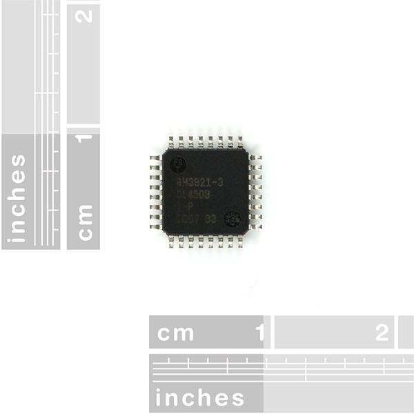
The processor we're using in the USB Doodad is an AVR ATmega328P.  This very capable processor is at the heart of the popular Arduino educational microcontroller platform.

The two most common packages for the ATmega328P are the PDIP-28 and the TQFP-32.

  <Good place to insert picture of PDIP vs TQFP>

Because the whole purpose of the USB Doodad is to use surface mount components, we want to use the TQFP-32 package.

Image courtesy of SparkFun.


Armed with a USB Doodad prototype board that Ross etched, I thought it was time to try soldering this chip.

There are several ways to solder SMT ICs.  A good guide is in this SparkFun SMT tutorial.  The method I used was using solder paste and hot air.

In order to do hot air soldering, I use a "hot air rework station" which I bought for about $80 in China.  I found another one at Ameritronics which looks very nice, nicer than mine.

Ideally, I'd use a syringe of solder paste, but I don't have one.  Instead I used the paste I covered previously.

I applied my solder paste with a jeweller's screwdriver.  Not a very precise way of doing it, but it did the job.  I applied one thin line of solder paste along the line of IC pads, then squished the chip pins into the paste.  Then I ran some liquid flux along the pins on all four sides of the chip.

Next, I used the hot air to melt the solder on each corner of the chip.  That was to fix the chip into place.  Finally, I ran the hot air along each side of the chip in turn.  The combination of pins, solder paste and flux means that when the solder paste melted, it blobbed around each pin.  I didn't get any bridges between pins, but if I had, I'm confident I could have fixed it with some desoldering braid.

My success makes me think that beginners could solder it too, if they had the right equipment (a hot air rework station).  And if we had a board with a solder mask (as we'll surely have for Doodad a little further down the track), I think beginners could do it with a regular iron too, if they had a video to watch showing how it's done.

Well, that's how I soldered a TQFN-32!

Tuesday, November 2, 2010

USB Doodad 2: Board design and layout

Some time ago, Ross and I discussed and agreed on what we'd like this board to do (and perhaps just as importantly, what we don't need it to do).  How do we get from this stage to something people can assemble?  One way is by making a prototype.

A prototype lets us:
  • Try out the circuit and different variations,
  • Try out the PCB layout and variations,
  • Try out the software and variations, and
  • Try out different assembly ideas.
Ross started off by finding a project in Elektor, a famous English-language electronics magazine produced in the Netherlands.  What it has in common with the Doodad is that it uses an ATmega328P microcontroller, and uses V-USB to do software USB.

Using that project as proof of what is possible, Ross designed the circuit to our requirements, and did a PCB layout.  Because we may use the underside of the board for other purposes later, Ross faced the additional constraint of having to make the board single-sided.  He and I discussed and improved the circuit and the layout several times, and Ross reworked the circuit and layout to match.

In particular, if we use the same pins as the Elektor project, we'd only have 14 pins free for driving LEDs.  Ideally however, we'd like 16 LEDs.  We think by reassigning some pins, doing away with some features (for example, a bootloader exit button, and a reset button), and being creative with some circuit ideas (for example, using a resistor network to run a number of switches off some otherwise-unused ADC pins), we believe we can recover enough pins to give us 16 LEDs.  We'd also like to be able to use the SDA and SCK pins on the expansion port so we can easily attach I2C devices such as sensors and storage ICs.

In order to do this pin experimentation, the board currently has a number of solder pads we can link to reroute various signals.  Here's the current layout:
USB Doodad PCB artwork (v15)
On the left is the expansion port (+, - and two data pins).  On the right is the USB finger port.  Along the bottom is where the LEDs and dropper resistors will go.  In the top right are the USB analog components.  In the middle is the microcontroller, and to each side are the power supply and clock components.  The switches go in the top left.

While this board may not do everything we want it to, it will let us answer a lot of the questions we need to answer before we can produce a final board ready for sending to a manufacturing house.

I want to say that Ross has done a top job: The single-sided layout constraint is pretty fierce, and the quality of the prototype board is easily as good as a bought one.  I am learning a lot working with him.

Monday, November 1, 2010

USB Doodad: An SMT exercise project

Surface mount soldering doesn't have to be scary!

Way back in the distant past when I learned electronics, components were "through hole". That means that components such as resistors had a wire out each end, and these wires were bent and passed through holes in a circuit board, then soldered.

An example through-hole board.

These days, through hole technology is on the decline. It's becoming harder to get the newer integrated circuits in through-hole form. In its place, more and more people are using "surface mount" technology to build circuits. With SMT, components are often in the form of a tiny block, which is placed on a circuit board, directly in contact with the circuit board tracks, then soldered into place.

An example SMT board.
Many people I've spoken to think that using SMT is harder than through-hole. Sure, many SMT components are very tiny, but it's quite easy to buy larger sized SMT components.

As a project at our hackerspace, Connected Community Hackerspace, Ross McKenzie and I have been working on a project which shows people that doing SMT assembly is not as hard as people think.  We have deliberately used the largest size of SMT components to make assembly as easy as possible.

The board has a USB connector at one end, a small expansion connector at the other, and a row of 16 software controlled LEDs in the middle.

The primary purpose of the board is to act as a practical exercise in surface mount assembly.  The secondary purpose is to show how to use the V-USB software USB stack to make a USB device.  The third purpose is to give the Doodad some post-tutorial value, in a number of intentionally frivolous ways:
  • Persistence-of-vision toy. Wave it around or put it on the wheels of your bike. Enjoy making groovy flowing messages in the dark.
  • Secure password keystore.
  • Log-data-to-serial-flash data logger, where samples could be retrieved over USB at some later time.
  • “Messages waiting” / “processor load” / “build progress” indicator.
  • Multimedia keys (if your keyboard doesn’t have them).
  • Novelty breathalyser.
  • Countdown timer for car parking reminder.
Our estimate for the cost of this board is about AUD30, so it's well within hobbyist reach.

We plan to release the design for this project under an open licence, possibly the TAPR OHL, which means that others can copy this design.

The project has been designed to use a single sided PCB.  Although this makes the job of designing and routing the board traces much more difficult, being single sided means people can make this board at home.

For applications which require the doodad to operate independently of a PC, we plan to add a small Li-Ion battery and management chip to the reverse of the board.

More information about the project can be found in the USB Doodad Google doc.

Ross and I are making rapid progress, and I'll post more project updates here soon.

Tuesday, October 26, 2010

Making PCBs using the toner transfer method

Last year the folk at CCHS, my local hackerspace, did some work on producing PCBs using the photo resist method.

Because I don't have a UV box, and because I'd rather not keep buying UV sensitised PCB, I have been looking at the "toner transfer" method.

  http://www.riccibitti.com/pcb/pcb.htm

Most people use glossy magazine paper, or glossy inkjet paper.  I have been looking at other transfer materials.

Last year, I was using the slippery backing paper from sheets of labels.  This didn't transfer too badly, but I did have somewhat of a problem of small sections of track flaking away from the backing paper before I could do the transfer.  Also, I don't have much of the backing paper.

Last night I got to thinking of other transfer materials.  Something I can print on, but would be willing to give up the toner when it's heated.  I decided to try aluminium foil.

I've done some searching this morning, and it seems I'm not the first to think of using foil:

  http://hackaday.com/2006/05/27/pcb-fuser-for-toner-transfer-etching/

Well, I did several experiments last night, what I can report is that the tracks on the aluminium foil transfer very nicely to the copper.  If the heat is right, there's absolutely no toner left on the aluminium, and the foil can be quickly and cleanly peeled back to leave the tracks of toner on the PCB.


The artwork I'm using has SMT ICs of 0.6mm pitch, which means the tracks have to be really precise.  I haven't yet got one that's of sufficient quality to etch, but I think I'm very close.  Some of my attempts have had great tracks in the middle, but lost some tracks at the edge.  Some of the attempts have had 100% transfer to the copper, but are a little smudged.  I don't think this problem is because I'm using foil as a transfer medium.  Rather, I think it's a problem with the way I'm doing the ironing to transfer the image.  If I can refine the heating process, I think I can produce very high quality boards.  I'd expect to be able to do thinner than the 0.6mm our group can get with the photo resist process.

I think I'll look into getting a laminating machine.  More results to follow.

Saturday, October 23, 2010

Open letter to seek.com.au: Suggestions for improvement

From time to time I jump on seek.com.au to see what jobs are out there.  They currently have a boring-as-all-getup survey to gauge how Seek users find the website.  Buried in the survey is a text field which says "in what ways could the site be improved?".

Since I couldn't fit my suggestions in their text field, I'm posting them here, and I'll send Seek a link to here instead.


Goodness, where do I start???

Suggestion 0: Don't ask people "Please provide as much information as possible" then give them a 6-line text field to write it in.

I can list 20 more ways to improve your website.  Please keep in mind that lots of my comments below are about how to make reviewing a large amount of data as simple and as speedy as possible.

I am an experienced Software Engineer in Melbourne.  Naturally I look for jobs in the ICT classification, in the Melbourne area.

Job searching


Because I'm experienced, I could do jobs in several of the ICT sub-classifications.  Not to mention that many jobs are misclassified.  However your website only allows selection of one sub-classification at a time.

Suggestion 1: In the advanced search, allow users to select multiple subclassifications instead of just one.

Since your site doesn't let me do that, I'm forced to use "Any sub-classification".  That means I have to trawl through a LOT of jobs, most of which won't be relevant to me.  So it's vital that I can do that trawling as efficiently as possible. 
While I understand many people just browse on your site, I'm the kind of guy who wants to be sure he's read every ad.  So it's important to me to know where I got up to on my last visit.  At the moment I start from the top and keep reading until yesterday's or last week's ads start appearing.  But this is something the Seek website could do for me.

Suggestion 2: Have something like a bookmark, or a filter that says something like "show me only ads listed since I last visited".

Computers are very good at managing large amounts of data, and finding trends and correlations in that data.  For example, one of the little known purposes of your supermarket's loyalty card is so that the supermarket can use "market basket analysis" to identify correlated buying patterns.


If you want an example, head to the Jango music site.  Enter an artist.  Jango starts playing music, and you can say whether or not you like that song.  Your input, plus the listening patterns of Jango's other users, is used to start feeding you music from other artists.  Jango very quickly starts playing you only the music you like, and through this I have discovered many really cool music acts.  Go try it!

Suggestion 3: Use market basket analysis and other data mining techniques to say to a user "you liked that ad, you'd probably also like this ad".  Then show them those ads.

Suggestion 4: Take this idea further, and play "20 questions" with the user.  Show them two ads.  Ask them which they prefer.  Use their selection and some "affinity analysis" to find two more ads.  Or show an ad and ask the user to rate it "hot or not".  Twenty answers can whittle a million choices down to one.  Twenty questions, and Seek can then say "based on that, here are the jobs we think you'll love".  Implemented well, Seek could use this in a marketing campaign as "simply the fastest way to find the job that's right for you".

Presentation


Trawling means I scan a whole page of jobs, then go to the next page.  I use space or PgDn.  But when I get to the end of the page, I need to take my hands off the keyboard, point with the mouse and click Next.  That takes time I don't want to spend.  (I’ll cover the major reason I use the keyboard later on).

Suggestion 5: Provide keyboard shortcuts so one can go to the next page without using the mouse.

Since I have to look at every single ICT job in Melbourne, there's a lot of noise I have to trawl through.  Let's assume the user has a "hot list" and a "not list" of words.

Suggestion 6: Given the "hot list", highlight any of those words that appear in that ad.

Note, these keywords are not definitive enough to warrant me searching on them.  Plenty of great jobs in a certain area don't use meaningful keywords.  Keywords are hints, not search keys.
Conversely, there are a bunch of technologies out there that I have no experience or interest in.  If a term for that technology appears in an ad, it's a pretty fair bet that the job’s not for me.  So I really don’t want to put any brain power into that job.

Suggestion 7: Given the "not list", grey out the whole ad if any of these words appear.  It still appears in the jobs listing, but greyed out.

Now let’s look at how you’re using screen real-estate.  I have an LCD monitor that’s 22” from corner to corner.  That’s by no means uncommon; you can buy one from MSY for under $180.  22” corner to corner is 19” side to side.  Let’s look at how that space is used, left to right:

  • 2.5” absolutely blank space
  • 2.5” refine your results (only top 5% of column used)
  • 1” job selection checkbox
  • 2.5+” location, and maybe salary
  • 5.5” the text of the ad
  • 2.5” some “helper” icons (only top 10% of column used)
  • 2.5” absolutely blank space

You are spending 5” in absolutely blank space!  And you are spending 5” on tools and search refinement that could live at the top/bottom of the page.  You’ve reduced my nice 19” monitor to a 9” monitor, smaller than my first 12" monitor in 1989!

You might say “well, ads (and web pages in general) look bad if they’re too wide so we have that space to burn any way".  But what happens if I want to use the left half of my screen to look at Seek ads, and the right half to compose a cover letter?  Or if I have a smaller screen?  Or I’m looking at it on a smart phone?

Fortunately, the whitespace on the sides disappears when I resize the window smaller.  But everything else stays the same.  But I do end up having to sideways scroll the page to get the ads centred.

Suggestion 8: Put the 2.5” of “refine your results” stuff, and the 2.5” of “helper” icons at the top/bottom of your page, and make sure your page doesn’t need sideways scrolling on smaller screens.

As mentioned, I do a lot of scrolling through ads.  I rely on words of interest passing by and catching my eye.  You have a pink box that highlights an ad as the mouse goes over it.  I’m sure you thought that was a great idea.  But the flashing of that pink box as ads go under my mouse is INCREDIBLY distracting when I’m looking for keywords. And it makes your site look like someone’s CSS homework.  Just because it’s possible doesn’t mean it’s a good idea.

Suggestion 9: Please, lose the pink highlight.  Please?

One thing that really bugs me about Seek’s website is that once an advertiser retires an ad, Seek loses all memory of it.  For example, let’s say there’s an ad for a good job.  I bookmark the ad, and apply for it online.  Then the advertiser gets enough interest that they retire the ad, because they really don’t need any more candidates.  Next I get a call for an interview.  So I go back to the bookmarked ad to review what the advertiser wanted, and GRRR, it’s not there any more!  How can I prepare for the interview?

Suggestion 10: Except in the case of an ad that was offensive or illegal, if someone has the URL, show them the ad, even if it’s been removed from the public listing.

So, in order to cope with the above, I have to print out all the ads I’m interested in.  Means I can’t use your tools to manage my applications, but at least I've still got the ad after it's retired.  But what about if I want to go back to the online version?

Let’s say I was after job number 18393608.  What I have to end up retyping is:

  http://www.seek.com.au/job/c-engineer-adelaide-based-satellite-communications-next-g/melbourne/18393608/28/1/

That’s a lot of annoying typing, and if I made a mistake in typing it or copying it down, a great job could get away from me.

Suggestion 11: Rewrite your single job pages as (to use the above as an example): http://www.seek.com.au/job?18393608 or similar.  Note, short URLs are no easier for unscrupulous companies scraping your website for jobs, than long ones, so there's no reason to have long ones.  Long ones just make life difficult for schmucks like me.

Data quality


Remember I’m in Melbourne? I have a family and I’m not interested in moving or working outside of Melbourne, so in the advanced search, I always choose Melbourne.  So I’m baffled that I keep seeing ads that aren’t for Melbourne, like the example ad from above.  Please, why does this ad show up if I searched for Melbourne?

This is not a one-off: I’d estimate about 5% of your ads are similarly (and like the Adelaide Next-G ad above, I’d certainly say deliberately) misfiled.

Suggestion 12: Give people a way of reporting such ads (but see below).

Another extremely annoying thing is when recruitment companies put in ads for themselves.  In other words, there’s no job, just a company putting in an ad because they want to get you on their books.  Really, this isn’t why I visit Seek.

Suggestion 13: Ban ads for recruitment companies.  An ad without a job behind it just undermines the quality of Seek’s database.

What’s also annoying is speling misteaks in job ads.  I’m one of those people who notices every single spelling mistake, and when I’m reading ads, it’s like mental speed bumps.  Don’t advertisers know how poorly it reflects on them? 

Suggestion 14: When an advertiser places an ad, run it through a spell checker, and if there are typos, give the advertiser the chance to fix them.  Since ads contain many acronyms and company names, give advertisers the chance to tell the spell checker that words it highlighted are actually correct, for next time.

All that raises another question: What are you doing to engage your users, Web 2.0-style?

Suggestion 15: Give users a score, called a “reputation”.  If they correctly flag ads with incorrect location, no underlying job, or typos, their score goes up.  Users with scores higher than a certain amount have proven themselves and are trusted, and their reports are acted upon immediately, rather than needing moderation by Seek staff or other high score users.  This would be in place of the current “Something fishy?”

Suggestion 16: Give advertisers a publicly visible reputation.  If they keep posting ads that raise the ire of your users, don't take ads from them.  Do you really want their business?  If you do, what does it say about your business?

What you get out of all this is improved data quality, which makes it more attractive for people to seek on Seek. 

Another part of Web 2.0 is inviting your users to produce content.  At the moment, the Seek model is “all push”: You produce content (ads) and Seek users passively consume it.  But Web 2.0 is a two-way street.

Suggestion 17: Do as eBay does: Let users give feedback, and allow them to ask questions of advertisers.

Suggestion 18: Consider the idea of web forums where job seekers can hang out, talk about their experiences, and create a community and buzz around the Seek name.

Suggestion 19: Implement an online suggestion box, and invite your users to tell you what you can do better.  Don’t bury it in the middle of a boring survey!

I’m in the position where I have to use your site, as it has great jobs.  Yet the user experience is pretty dated and frustrating.  In order to make my job-hunting life bearable, I’ve fixed as many of these suggestions as I can on my end, using a Firefox plugin called “GreaseMonkey”.  It lets me change web pages to be how I wish they’d be, and when I sit down to look for jobs, it’s as if you’ve done suggestions 2, 6, 7, 8, 9, 11, and 14.  So I have road-tested these particular enhancements.  (The other suggestions would need changes on your end of the deal, so I can’t use GreaseMonkey to fix them).  But when I go to look at jobs on another computer, I’m back in “lame Seek” land, and the pain comes back.

I’ve now spent about two hours of my time writing 2000+ words to you.  I hope you guys actually read it, and even better, implement some of them!

Suggestion 20: Call me.  Seriously.  If you’re not sure what I mean, I’d be happy to further explain some of these suggestions.  Or if you’ve implemented some of them, and want someone to road test them, I’m happy to do that too.  Just make your site a bit less painful, please?

Saturday, October 9, 2010

Replacing DS touchscreens (part II): When it starts to go right but something else goes wrong

Last article in this series, I replaced a Nintendo DS touchscreen, but in doing so, broke the touchscreen connector (whoops).  I ordered a new connector from GoldenBridge, but surprisingly enough, they didn't ship it until two weeks after I placed the order!  So including the shipping time, the connector ended up taking nearly a month to get here.  GoldenBridge, no cookie for you!

Well, the connector finally arrived, and I took the DS and the connector to our weekly hackerspace meeting.

I don't have any pictures at present, but the good news is that I was able to desolder the connector from the board, and resolder on the new connector.  Took me a few goes, and use of flux and desolder wick and magnification, but I did it.

Only problem is, when I was reassembling the board, I broke the slider off the power switch.  Ouch!

I ordered a new power switch from DealExtreme, and when it arrived, I replaced the power switch.  Put it all back together and now I have a working Nintendo DS again.  I'm now out of danger of being disowned by the kids!

Monday, July 26, 2010

Touchscreen update

It's been a very long time since I've posted any articles.  However I've been working slowly but consistently on my touchscreen.  I'll have some more info later, but here's a sneak preview:

New touchscreen, wood case, direct USB.

I know, terrible photo, but that's the best my phone cam can do.  It looks heaps better in real life.  

This is a straight USB device, connected directly to my PC, and with no need of an Arduino.  As far as the PC is concerned, it looks like a USB mouse, except that the coordinates are absolute, not relative.

There's a microcontroller inside the case: A Teensy 2.0 running LUFA.

More details to follow!

Friday, February 26, 2010

International Space Station radio link-up

I just had a lovely evening at my kids' primary school.  A group of staff, parents and amateur radio enthusiasts have worked for months to organise a very special event: A radio link-up with the international space station.

To talk to the ISS, some local amateur radio enthusiasts hooked a phone line up to the PA, and this phone line went to Shane Lynd of Glendon, Queensland.  Using his aerial, radio equipment and phone patch, we were able to talk with astronaut Timothy "T. J." Creamer while the ISS was within line-of-sight of Glendon, which was about six or seven minutes.

The link-up was arranged by Tony Hutchison of Kingston SE, South Australia, who coordinates ARISS (Amateur Radio on the International Space Station).  ARISS lets crew members talk with family and schools, and provides backup comms with the station.  There's a nice video about Tony's work here

  http://www.youtube.com/watch?v=2KL8TGTUBTU

The students took turns to say their name, ask their question, and finish with "over".   Here's the list of questions, plus my unreliable recollection of the answer T. J. gave [and some comments by me]:

  1. At what stage in your life did you decide you wanted to be an astronaut?

    He said it wasn't a sudden choice, a lot of things he'd done beforehand prepared him for it and when he had the chance, he said yes.  [His bio is here]

  2. Does living in a zero gravity environment cause long term health problems?

    There are changes to bone density, to the muscles of the heart, and even to the structure of the eye.

  3. How far have astronauts ever been in space?

    To the moon.  Most people don't realise that only 12 people have been to the moon.  Everything else has been done in low Earth orbit.

  4. Who was the youngest astronaut to go into space? How old was she or he?

    T. J. didn't know the answer to this one, but he suggested that the student go to nasa.gov or Google for it.

  5. How do you exercise in space?

    He said he uses a treadmill, with bungees that keep him in place so he doesn't float away.

  6. How did you get into space?

    He said he was launched on a Soyuz rocket from Baikonur Khazakstan.

  7. What if there is a fire? Can you get rescued?

    He said that the space station is designed so that in general, things can't catch fire.  But if there was a fire, they'd cut the power and the fire would likely go out.  They can also use fire extinguishers.  If the fire was too serious, they could come home in the Soyuz capsule that is always docked to the station.

  8. What’s the most interesting thing about space?

    He said floating around, and looking at the Earth.

  9. How do you drink in space because there is no gravity in space?

    He told us about how they drink from fluid pouches.

  10. How do you control the space ship when it is floating in space?

    He said that attitude control is done with gyrodynes [but I think he means control moment gyroscopes, as gyrodynes are a type of aircraft].  If the gyrodynes become saturated, small thruster rockets take over to correct the situation.

  11. Are there aliens in space?

    He said he hadn't seen any, but he'd sure be glad to meet and talk with them.

  12. How do you sleep in the space station?

    He said he zips himself into his sleeping bag, that has straps which stop him floating around.  He said he sleeps very well.

  13. What is your favourite food you eat in the space station?

    Fresh fruit.  He said it was great when the Space Shuttle brought up some fresh fruit.

  14. What do you do on the space station to relax?

    He mentioned that he likes to go into his bedroom and read or use the internet to research things.  [He also likes running]

  15. What happens if you run out of air?

    He said that this is managed pretty closely from the ground, so it's unlikely to happen.

  16. What happens to all the rubbish from the space station?

    All the trash gets put into the Progress resupply vehicle, which is undocked and deorbited.  The vehicle and the trash burns up in the Earth's atmosphere.

  17. How often do you have to do space walks to make repairs to the space station?

    He said that they don't generally go outside to fix things.  He said that he's done spacewalks, but he's not scheduled to do any spacewalks on this expedition.

  18. When you are in space are you ever nervous about anything?

    He said that in general, he's not.

  19. When you swallow your food, does it feel funny in your stomach when in zero gravity?

    [out of range]

Unfortunately the 19th question couldn't be asked, as the station had moved out of range.  I feel sorry for that student.  If I was that student, that would be one of my "life's regrets".  (And I have so few)

In all, well over 200 people enjoyed the evening.  A big thank you to T.J., Tony, Shane, the local amateur radio enthusiasts, and all the others who made this possible.  It was certainly a night I'll never forget!

Wednesday, February 24, 2010

Computer assisted Chinese (part VII): Touchscreen 5

Last entry, I had the larger touchscreen working with X, and I worked out how to map the touchscreen data to a rectangular area on-screen.  This time, I will try to get a Nintendo DS touchscreen working with X.

Although my ultimate goal is to make a true USB device, for the moment I'm going to use an Arduino as the microcontroller. 

  http://www.arduino.cc/

The Arduino has an FTDI FT232RL chip on it.  This speaks USB on one side, and TTL-level RS-232 on the other.  On the Arduino board, the FTDI's serial port connects to pins 0 and 1 of the Arduino, which is the microcontroller's UART port.  This lets you send information to and from the microcontroller over USB, and what the PC sees is a USB serial port.

My plan is to make a serial port based touchscreen which emulates one of the existing serial port touchscreens supported by Linux.  Hopefully this means I don't have to write any kernel code.

I looked around in the kernel's drivers/input/touchscreen directory for the serial port touchscreen driver with the simplest protocol.  The most likely candidate seemed to be the driver for the 3M MicroTouch.  It's a five byte protocol, and the driver looks pretty simple.  I'll come back to the protocol later.  For the moment, I want to see if I can read the touchscreen ok.

A touchscreen is a sandwich of two transparent plastic plates.  Each plate is covered with a conductive film, and one plate is printed with tiny plastic bumps to keep the two plates apart when not being touched.  You can find out more about how touchscreens work here.

My touchscreen has four wires.  These wires must be connected to the Arduino board, so I made my own "breakout" board.  I used one of the Sparkfun connectors I bought to fix my Nintendo DS touchscreen.

Soldering the touchscreen connector was "fun".  Remember, there's four conductors in the space of 1.5mm.  I had a lot of problems with solder bridges between the pins.  I eventually solved this problem by using a jig made of polyimide tape with three fingers, which fit between the pins and make a physical barrier to prevent solder getting from one pin to the next.  After completing the soldering, I removed the fingers.

Polyimide tape is a heat-resistant film that is sold by DuPont under the name of Kapton.  Cheap polyimide film can be bought here.

The wire I'm using is wire-wrap wire.  Four of these wires next to each other give exactly the right spacing.

In order to prevent the tiny wires on the connector from breaking, I wanted to put the connector on a board. I didn't want to glue the connector, as there's a risk that glue will get inside. So I made my board out of a small piece of unetched printed circuit board, and soldered the connector to the board. The 4-pin connector has solder pads on the bottom: how to solder it to the board?

Recently I bought myself a small tub of solder paste.  This is a mix of microscopic solder balls, suspended in a liquid to make a paste.  Although it looks a dull grey to the eye, I looked at it under the microscope at our hackerspace, and yes, it's a sea of unbelievably tiny balls.  How cool!

I used a pen to draw the dimensions of the connector onto the end of the PCB, then used a rotary cutting tool to remove the copper where the touchscreen conductors go.  There's still copper underneath the solder pads on the connector, but no copper under the touchscreen wires.

Using a jeweller's screwdriver, I applied a tiny amount of solder paste to the copper of the board where the connector's solder pads will go, and placed the connector.  Holding the connector in place with my finger, I touched the soldering iron to the copper next to the connector.  The copper conducted the heat into the solder paste, and I could see the paste turn from a dull grey to a lovely silver.  I could also see surface tension pull the solder into a nice shape around the solder pads.  Result: One nice strong strain relief for the connector and the wires.  This solder paste worked very well, and I will definitely use it more in the future.  I bought it very cheaply here.

Next, I used 4 header pins to join the wire-wrap wire to the four-conductor flexible ribbon cable, and used 4 right-angle header pins at the other end to make a plug for the Arduino.  To finish off. I used hot glue to lock the ribbon cable in place at both ends.  Here's the result:


The breakout board is a bit rough, but it's a prototype.

(If you have keen eyes, you may note a button attached to the lower Arduino connector.  More about that later)

Well, that's the mechanicals done, now for some software!

Tuesday, February 23, 2010

Replacing DS touchscreens (part I): When it all goes wrong

The other day I was talking about the cheapie touchscreens from DealExtreme:

  http://www.dealextreme.com/details.dx/sku.3245

I bought a few for experimenting with, and one for replacing the touchscreen in my sons' Nintendo DS, as that touchscreen has developed problems.

To find out how to replace the touchscreen, I watched these guides:


  http://www.youtube.com/watch?v=5a1AIWYXPmg


  http://www.youtube.com/watch?v=lir1HCupK9Q

They make it look so easy!

Anyway, I successfully opened up that Nintendo DS, and was able to split the old touchscreen from the LCD and replace it with a new one. The problem came when I tried attaching the new touchscreen to the connector on the PCB. That connector has a tiny black plastic lid, and unfortunately for me, one of the legs on the lid broke off.  You can see the connector here:


That connector is tiny as!  To give you an idea of scale, the touchscreen ribbon cable you can see in the lower left is 2.5mm across: Just 1/10th of a inch!

Without the lid, the connector doesn't push down on the touchscreen cable, and the touchscreen doesn't work.  What to do?  Without a working DS, my kids will kill me!

I thought of trying to hot-wire the touchscreen cable to the board, either directly or via four tiny wires, but I couldn't think of a way that wouldn't risk damage to the PCB, so I decided to buy a new connector.

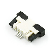
The first place I looked was SparkFun.  I found this connector:


(Click on image to go to the product page)


Although the shape is different, they are only about US$1 each, so I bought a few.  Actually, I bought them from SparkFun's local distributor, Little Bird Electronics.

The connectors arrived in about a week, and when I got them, I noticed something rather unfortunate: The connectors on the Nintendo DS PCB are designed to have the contacts on the touchscreen facing down, whereas the SparkFun connectors are designed to have the contacts facing up.  I don't think that's going to work!

In order to confirm this, I spent more than two hours at our hackerspace, soldering wires onto those four pins under a microscope.  And yes, that connector is the wrong way around and not suitable.

So, I did some more web digging, and found a company called Golden Bridge in Hong Kong.  It seems they're not dissimilar to Deal Extreme, and they have what appear to be the proper DS connectors:


(Click on image to go to the product page)


I ordered a few connectors a week ago, and I'm waiting for them to arrive, which they should do any day now.  Unless they arrive tomorrow, I won't get them in time to solder at hackerspace.  Which is unfortunate, as if my kids don't get their DS back soon, I think I'm going to be buying them a new DS.  Either that or I think I'll have to leave home...

Wednesday, February 10, 2010

Computer assisted Chinese (part VI): Touchscreen 4

Last article, I had a working touchscreen where the whole of the touchscreen surface was mapped to the whole of the display.

Skritter is a flash-based web app.  In scritter, there's an area in the middle of the window in which you can use your input device to enter the strokes for the character:


So I have the requirement that I want to map the touchscreen area just into that rectangular area.

Here's another requirement: A 15cm x 9cm touchscreen is designed to fit over a display, not sit on one's desk.


It's too large to comfortably write on, as my wrist hits the surface when writing and throws off the cursor. So I only want to use a small area of it.

And since I eventually want to build this with a cheap nintendo touchscreen, not a full-sized one, I'd like to just use one corner of the large touchscreen.

Further, I want size and aspect ratio of my small corner of the large touchscreen to be roughly the same as for the nintendo touchscreen. Fair enough.

But it gets better: When I finally use the nintendo touchscreen, I want the aspect area of that touchscreen to be the same as Skritter's on-screen drawing area. Since the aspect ratio of the Skritter writing area is slightly different to the nintendo touchscreen area, I will only use about 85% of the nintendo touchscreen area.

So, somehow I have to map a small corner of the large touchscreen, onto this particular on-screen rectangle.

The 11-eGalax.fdi file mentioned in the last article has a line of calibration data:
<merge key="input.x11_options.Calibration" type="string">32 3990 48 3990</merge>
Those four values are the data values one should expect to get from the touchscreen when touching the minimum x, maximum x, minimum y and maximum y positions on the touchscreen. The reason we can provide the numbers is to allow for variations in the properties of each touchscreen, although in general, the values will be around the minimum and maximum values the touchscreen can produce. But what if I fake these values?  Can I use this to trick X into mapping one area onto another?  Let's try...

One thing to note is that from my testing: I've found that the X axis and the Y axis are reasonably independent of each other: Running the stylus along a horizontal or vertical ruler on the touchscreen shows one axis changing a lot but not the other.  Therefore I think the number crunching for the X and Y axes can be done independently.

Mapping an input range of numbers onto an output range of numbers isn't hard. We can visualise the map as a graph, where the X axis shows the input range, and the Y axis shows the output range. The limits of the input and output range correspond to two points on the graph. We can then find the linear equation which describes the line, and once we know that, find the output value for any input value. This should map the touchscreen area to the on-screen area, but also, if we reverse the mapping and feed in the dimensions of the screen, we should be able to find the four calibration values we need to give us the desired mapping.

The first thing I did was work out how much of the touchscreen I want to use. I first considered the case of the nintendo touchscreen.

The pixels on my LCD display are square, so the aspect ratio is 1:1. When the web page is fully maximised, the size of the Skritter writing area on my screen is 347 pixels by 402 pixels. That's an aspect ratio of 0.86. I want to keep the same ratio on my touchscreen.

If I place the nintendo touchscreen with the long axis vertically, the active area is 47.5mm across by 63.5mm high, which is an aspect ratio of 0.75.  Note the two aspect ratios aren't the same.  If I want to keep the aspect ratio the same, I'll have to give up using a small area of the touchscreen.

If I map the width of the touchscreen to the width of the Skritter writing area, the height of the part of the nintendo touchscreen I'll be using is 47.5mm / 0.86 = 55mm. (I can use the remainder for not-on-screen special functions).


Note this picture is not to the same scale as the previous picture.

I then got an index card and cut out a rectangle 47 x 55mm.  I can then place this on top of the larger touchscreen to show me the useable area of the smaller touchscreen:


For comparison, here's the nintendo touchscreen on top of the larger touchscreen:


(The colour difference is because I took the two pictures at different times of the day)

Then I ran the evtest program again,and recorded the touchscreen values for the top left and bottom right corners of the uncovered area on the card.  (The values are backwards because I'm using the touchscreen rotated by 180°).

Tscreen Point X data value Y data value
top left 1940 1850
bottom right 950 203

Skritter Point X data value Y data value
top left 504 285
bottom right 851 687

Screen Point X pixel Y pixel
top left 0 0
bottom right 1680 1050

Now, time for some number crunching.  Treating the X and Y axes separately, we can find the m and c in y=mx+c to map the touchscreen coordinates to screen coordinates.  Then, using x = (y-c)/m, we can feed in the boundaries of the screen, and found out the effective values if the touchscreen was big enough to cover the whole screen, and mapped our touchscreen area onto the Skritter writing area.

I cooked up a spreadsheet to do the number crunching.  I typed in all the coords, and it spits out the four "calibration values" I needed.  You can find the spreadsheet here:

  http://spreadsheets.google.com/ccc?key=0Av3tC4mEgkZPdEl5cl9IR09RdzktUmJvWjEwQURoelE

If I use the data from the tables above, I get the following four values:

Min X 3378
Max X -1415
Min Y 3018
Max Y -1284

Note that two of the four numbers are negative.  That's to be expected.  It just means that with the mapping we have, the lower right corner of the touchscreen is inside the display area.  That's ok for us, because we'll never be sending negative values anyway.  (I'm feeling pretty lucky that whoever wrote the HAL and X stuff didn't disallow negative calibration values....)

So, then I plugged these values into the 11-evdev.fdi file:
<?xml version="1.0" encoding="ISO-8859-1"?>
<!-- 10-synaptics.fdi is claiming all input.touchpad's as its
     own. This file is meant to be loaded afterwards and to undo
     any wrong assignments it did.
-->
<deviceinfo version="0.2">
  <device>
    <match key="info.capabilities" contains="input.touchpad">
      <match key="info.product" contains="eGalax">
        <merge key="input.x11_driver" type="string">evdev</merge>
        <merge key="input.x11_options.Calibration" type="string">3378 -1415 3018 -1284</merge>
      </match>
    </match>
  </device>
</deviceinfo>


Enough talking, what happened after I restarted HAL and X?  Well, it worked first time!  A light touch to the corners of the restricted touchscreen area goes straight to the corners of my on-screen input area.  I love it when something works first time!  To celebrate, I went and practised Chinese characters for three hours.  So much nicer with a pen rather than a mouse!

What's next?  Well, now that I have the larger touchscreen working, I want to get the cheapy nintendo touchscreen working.  Oh, and practice Chinese more :-)

Computer assisted Chinese (part V): Touchscreen 3

In the last article, I was getting good sample data from the touchscreen.  But does it work in X? Sadly, it doesn't. Or at least not straight away.

(Note, you'll need to make sure the xorg-x11-drv-evdev package is installed).

When a new USB device (such as that touchscreen) is plugged in, the kernel tells the HAL subsystem. HAL notices the new input device, and tells X about it, and X starts listening to the new device. The beauty of this system is that X can respond correctly as input devices are connected and disconnected from the machine.
The problem is that the standard Fedora kernel treats this kind of touchscreen as an evdev device (good), but HAL makes a mistake about what kind of device it is.  There's a rule in HAL which says "any touchscreen which I don't know about must be a "Synaptics" touchpad". This bad guess gets passed onto X, and X tries to interpret the device as a Synaptics touchpad. Since the device (by the time it gets to X) is really an evdev device, X doesn't know how to handle the touchscreen properly.

So in order to get the touchscreen to work, I had to work out how to convince HAL that the touchscreen was an evdev device, not something else.

This problem has also been experienced by others, and is covered in Fedora bug 473144. To cut a long story short, the most convenient solution is to create a file which tells HAL which kind of input device it really is. Comment 45 of that bug contains a suitable .fdi file:

  https://bugzilla.redhat.com/show_bug.cgi?id=473144#c45
<?xml version="1.0" encoding="ISO-8859-1"?>
<!-- 10-synaptics.fdi is claiming all input.touchpad's as its
     own. This file is meant to be loaded afterwards and to undo
     any wrong assignments it did.
-->
<deviceinfo version="0.2">
  <device>
    <match key="info.capabilities" contains="input.touchpad">
      <match key="info.product" contains="eGalax">
        <merge key="input.x11_driver" type="string">evdev</merge>
        <merge key="input.x11_options.Calibration" type="string">32 3990 48 3990</merge>
      </match>
    </match>
  </device>
</deviceinfo>
That bug mentions a file in /etc/hal/fdi/policy called 10-synaptics.fdi. I don't have a file of that name in that directory. Instead, on my machine, it's in /usr/share/hal/fdi/policy/20thirdparty. So I decided to copy the file from that bug report into a file called 11-evdev.fdi in that directory. Then I had to restart HAL in order for it to see the new .fdi file:
  service haldaemon restart
After doing that, I can now see the touchscreen in the output of lshal.

What happens when I restart X? Well, the touch screen works. Sort of.

Note that the maximum X and Y values in that file for the touchscreen axes are 3990. But the evtest utility reported maximum values of 2047. I found that if I use 3990, I can only use the touchscreen for the top left quarter of the screen. Obviously those numbers are wrong for my touchscreen.

When I changed the numbers to 32 2000 32 2000, the touchscreen could point at any location on the X display. Success!

So, what I have now is a working touchscreen, and a setup which maps the whole of the touchscreen to the whole of the display. For reasons I'll go into soon, that's not what I want. But, good progress so far.